silverstone
Solar Enthusiast
- Joined
- May 3, 2022
- Messages
- 1,044
Hi,
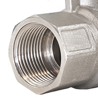
I bought these Battery Terminals from Aliexpress to use as my Battery Terminals. They claim to be rated 200A each but I plan to use them at 100A only.

I recently however talked with a friend who told me that copper is a quite soft material and won't really resist a lot torque (especially if I overtorque). Which is why we always use (either of) in industrial environment:
- Bolted connection (Bolt + Washer + Washer + Conical Washer + Nut)
- Clinch Nut embedded in the Copper Busbar (Bolt + Conical Washer + Washer screwed into the Clinch Nut)
I'm not sure if this is mainly due to the extreme amount of vibrations, thermal cycling, or probably a combination of both.
The internal thread is M6. I might get away to drill that out and use a M6 bolt + Washer + Conical Washer + Washer + Nut instead (galvanized Steel).
The external thread is M8 and that of course I cannot drill out.
Any thoughts ? I thought I remember seeing some videos on Youtube about Andy from Off Grid Garage using terminals like these. And he also used tapped & threaded busbars for his battery shelf ...
EDIT: the material is probably Brass, not pure Copper, even though the listing on Aliexpress is quite confusing about this aspect ...
I bought these Battery Terminals from Aliexpress to use as my Battery Terminals. They claim to be rated 200A each but I plan to use them at 100A only.
I recently however talked with a friend who told me that copper is a quite soft material and won't really resist a lot torque (especially if I overtorque). Which is why we always use (either of) in industrial environment:
- Bolted connection (Bolt + Washer + Washer + Conical Washer + Nut)
- Clinch Nut embedded in the Copper Busbar (Bolt + Conical Washer + Washer screwed into the Clinch Nut)
I'm not sure if this is mainly due to the extreme amount of vibrations, thermal cycling, or probably a combination of both.
The internal thread is M6. I might get away to drill that out and use a M6 bolt + Washer + Conical Washer + Washer + Nut instead (galvanized Steel).
The external thread is M8 and that of course I cannot drill out.
Any thoughts ? I thought I remember seeing some videos on Youtube about Andy from Off Grid Garage using terminals like these. And he also used tapped & threaded busbars for his battery shelf ...
EDIT: the material is probably Brass, not pure Copper, even though the listing on Aliexpress is quite confusing about this aspect ...
Last edited:
 .
.