DoctorBrucey
New Member
I see costs can quickly add up! £700 battery + £80 smart shunt is a lot more than just the £550 battery I had initially. I'm prepared to invest if it's as important as you say. You don't think I can get away with just the Fostar battery and no smart shunt?The smart shunt is worth installing with any battery but does not show what's going on inside the battery. A battery with a Bluetooth BMS will show exactly what is happening with the 4 cells that make up the battery, such as each cell voltage, cell temperature , indicate that the battery is charging or discharging, battery SOC. If a protection event occurs it indicates what happened, for example, the battery charge volts was too high. Also with a suitable app its possible to modify the protection levels, for example the overcurrent protection set at 200 amps is rather high for your modest application.
With the Bluetooth communication impending possible battery faults are easy to see, this enables correction procedures, for example changing the charge volts. In the very rare worst case, a battery fault can be diagnosed more easily making any warranty claim painless with companies like Fogstar in the UK .
(Warranty claims with Renogy or Eco worthy are extremely difficult and time consuming to process, technical help is almost non existant and any replacement you are extremely lucky to get may not be in UK stock, involving shipping problems. )
You know the expected current and specification of the unit. Use suitable cable for the current and ensure any volt drop is acceptable,
Voltage Drop Calculator | 12 Volt Planet
Use our Voltage Drop Calculator to select the correct Cable for your campervan, motorhome or boat wiring application. Auto and Marine Electrical Components from 12 Volt Planet - Cable Size Calculatorwww.12voltplanet.co.uk
If you go to the cable section of 12v Planet the maximum current rating of each size of cable is shown. Often in 12 volt systems you use a 'fatter' cable than the current specification to get a reduced volt drop.
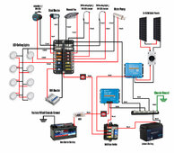
The DC to DC charger from Victron is a nominal 30 amp unit. The fuse must be higher than 30 amps to prevent false trips, select 125 to 150 %. ( in practice the Orion current exceeds 30 amps on the input and output so a 50 or 60 amp fuse is recomended by Victron.
Once the fuse is closed check the cable is rated for this current.
The MPPT is rated at 20 amps, so a 30 amp fuse is needed , a 6mm2 cable can carry 50 amps. Checking for volt drops , assuming a 1 meter run to the battery, using the calculator for 20 amps, volt drop 0.13 volts. Since with 200 watts the current will be lower than 20 amps a volt drop of around 0.06 volts is OK.
Regarding the Video help from Greg, his 12v advice is good but the inverter and AC side is sometimes non complianent ( Greg and myself have had email communication discussing some issues).
Typical failures in camper conversions, cables too small, no or incorrect fusing, fuses in the wrong place, house battery negative and AC protective earth not connected to van metal/chassis/frame, batteries not secure clamped. The most dangerous failures are in the AC circuits and inverters with no or incorrect electric shock protection. There are standards that professional converters legally have to comply with, many DIY you tube 'experts', do not. DIY electrical work on a van conversion can be carried out in the UK without Inspection or professional input
Makes sense re: fuse size. So I just look at the amp rating for whichever device, find 125-150% of it, then get the closest amp-rated fuse rounded up?
I'm guessing for the rest of my appliances, because most of them will be installed quite close to the fuse holder (and they're not sensitive to voltage drops like a fridge) I don't need to worry too much about voltage drop?
Understood re: Greg. I won't be doing any AC / Inverter so should be fine. Also noticed he didn't earth anything to the chassis.
My plan is to use 3mm cables for all my 12v appliances (except heater, which will be 6mm). Then 16mm for the DC to DC charger (I know your chart says 10mm from DC to DC to midi fuse box, then 16mm to battery. Can I just use 16mm for both to save buying any 10mm wire?)
My only change will be with this inverter. Am I correct in saying that I'll need a 10mm cable for this? It runs at 400W (so around 35A in a 12V system). I'm placing a fuse holder very close to where this will be, so almost no voltage drop. Therefore, rounding up one gauge to be safe, I've calculated this to be 10mm. Then, I'll add a 50A fuse to this (between 125-150% of the 35A). Let me know if that makes sense, as it's the first time I've done this.
Last edited:


