diy solar

diy solar

Dead cell sample lines on JKBMS JK-B2A24S JK-BMS >> FIXED

keepsake

New Member
Joined
Jan 17, 2021
Messages
452
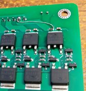
I have bought 5 of these JK-B2A24S active balancers over the past 3 years. JKBMS. Rather happy until one just broke itself.
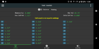
It shows me '--' for the cell voltage on cell 1 and cell 2, the rest are all fine.
This condition triggers the CELL COUNT IS NOT EQUAL message and so the balancer has disabled itself.
There is no way to workaround 0.00 at cell 1 or 2.
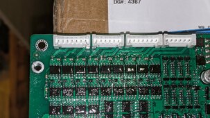
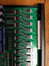
There are correct voltage right down the pins on the module, cells are fine, just erroneous sample inside black module.
When I fetch data on bluetooth it shows all good except 1 and 2.

JK bad --
Fri, 08 Mar 2024 04:58:25 DEBUG JKBMS tot=49.87v low=0.0v high=3.326v delta=3.326v soc=None%
c1=0.0v c2=0.0v c3=3.325v c4=3.323v c5=3.323v c6=3.325v c7=3.325v c8=3.323v c9=3.325v
c10=3.325v c11=3.325v c12=3.325v c13=3.326v c14=3.325v c15=3.325v c16=3.325v c17=3.322v

below is when all was good ---
Wed, 29 Nov 2023 04:39:24 DEBUG JKBMS tot=56.78v low=3.336v high=3.348v delta=0.012v soc=85%
c1=3.348v c2=3.348v c3=3.347v c4=3.344v c5=3.338v c6=3.337v c7=3.338v c8=3.336v c9=3.338v
c10=3.338v c11=3.337v c12=3.336v c13=3.338v c14=3.338v c15=3.337v c16=3.337v c17=3.338v

Cannot find any way to get help or service.
It seems a firmware revision could allow this type of failure to workaround and use cells 3 and up in the process.

And yes my system has always had 17 cells in the bank.
 

Attachments

  • Screenshot_20240311-135415_极空BMS -- and --.png
    Screenshot_20240311-135415_极空BMS -- and --.png
    288.7 KB · Views: 14
Cell 1 and 2 both fail at the same time:
makes me wonder if one lead wire is no longer connected, messing up two calculations for cell 1 and cell 2
check the lead wire to pos end of cell 1/ neg end of cell 2 ?
 
These bms units pull and push up to 2 amps into a supercapacitor. Active balancing. That's their purpose in life. So the mosfets or other switching devices, failed. It's just a shame with the other 22 circuits apparently good, and I only need 17, there isn't a workaround to use the 'still good' remaining part of the device.
 
Has anyone here had one of these fail and been able to get replaced or serviced ?
 
JKBMS model JK-B2A24S
I am finding the seller 'useasy' on ebay WON'T HELP ME. I bought it from him six months ago, and it has the two broken inputs.
He claims to be acting as AGENT for the manufacturer and won't allow me to diagnose dead cell inputs with manuf.
Ebay itself blocks direct communications between buyer and seller and in the end, INHIBITS warranty activities.
HELLO EBAY -- you made your commission -- stop blocking direct communication.
Anybody with thoughts other than -- don't buy from China !
 
When I substitute another identical JKBMS unit it shows fine, just this one. It stopped correctly reporting while we were at sea, on a cruise for 9 days.
 
There is a resistor inline on the board sized to blow at a set amps, if you can solder smd components it can be fixed.
 
Pic of the board I had fail on cells 8 and 9, you can see the capacitors and resistors in a row below the connectors. You will see one of the resistors is burnt out. I removed the resistor and on this board there was a spare next to it so I moved it across. For this board with 2A active balancing the resistor was a 1/16W 0.01 ohm resistor marked R01, this blows at 2.5A so for a board with no balancing, passive balancing or 1A active then it could be a different value.
 

Attachments

  • Supplied board.jpg
    Supplied board.jpg
    429.7 KB · Views: 18
wow -- i hate soldering surface mount
I first soldered in 1968.
will look as the seller is anal and expects a trans pacific shipment and me paying to return
seller claims 2 month swap, after that must return
I ordered another one and might just go down the slippery road he is forcing, etc
 
The left most pin is B-
B1 is next and must go on trace on the other side
B2 is 3rd and I don't see any blown characteristics in the photo
I will get a meter out tomorrow and see if I see something that way
 

Attachments

  • IMG_20240429_201314 jkbms.jpg
    IMG_20240429_201314 jkbms.jpg
    168.7 KB · Views: 6
By fixing 8 resistor I got back the cell voltage on 8 and 9, so check the other side plus check with meter on resistors etc. You will need sharp pointed probes on the meter if it was like my board, everything had been coated with varnish which you have to get through to get to the solder joints.
 
I see 500k resistance across resistor on cell 1 sample
all others are 0.5 ohm
Did you just jumper it ? Or bother to insert half ohm. Or is there a fuse for that part size that you used ?
If I jumper that part it is on the bottom side -- inclined to use the ole 30 gauge wire wrap solid wire I still have from the 80s.
pin 2 from right
 

Attachments

  • IMG_20240501_194532 bms bottom side top right chip.jpg
    IMG_20240501_194532 bms bottom side top right chip.jpg
    134.3 KB · Views: 5
Last edited:
What is the cause of our 'fusible links' blowing ? Is it fatigue ? Poor design ? Are fuses there to protect the bigger silicon based device(s) ?
 

Attachments

  • IMG_20240502_082946.jpg
    IMG_20240502_082946.jpg
    134.9 KB · Views: 3
Did you just jumper it ?
Do to the boards design mine had a spare resistor, so I took off the blown one and moved the good unused one across to replace it. Its purpose is to protect downstream parts from excess current. On my board with 2A balancing each sample line needs to take 2A so the resistor is sized to blow at 2.5A. Mine came ready blow out the box.
 
Can you post a photo of your board and where you found any spare fuse links ?
Or try to describe how I can be sure I'm not pulling one that's 'in play'

Hmm, maybe you are suggesting since I use cells 1 to 17, just steal a link from 18 to 24.

I've never gotten any surface mount solder tools. Can you post a link to a place you've been happy with and the tools you use ?
Thanks.
 
Back
Top