diy solar

diy solar

Do i have too much grounding on my system? - PV & Utility Earthing.

mrdavvv

Solar Enthusiast
Joined
Jan 14, 2020
Messages
404
Hello!.

This is my current system:
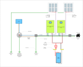
rect1444.png

So im wondering, is this OK?.

As you can see, i have 3 physical grounds, all of them separated.

Ground 1: Exclusive to the PV panels, and not connected to any equipment, just the aluminum racks for panels.
Ground 2: This is required from Utility company, and must be bonded with the neutral cable behind the meter.
Ground 3: I plan to add this grounding to the main panel, and it would be only used for the house loads. Currently i dont have any type of ground inside the house, as the originall installes didnt consider it important.... ideally i would brin ground #2 to the main panel, but the existing installation doesnt allow for more cables, so i would need to open the wall (Big PITA). I could also send the cable outside the wall but as its an AWG #8 it would look ugly. Somy plan its to add a new ground near the main panel (Ground #3).

Mainly because its difficult to bring Ground #2 inside the house to the main panel, as the original instalation didnt have any type of ground

- All grounds are separated by at least 5mt between them.
- Grounds are made from a 2.5mt copper bar with #8AWG.

----

So what do you think about this installation?, im doing something wrong?.

-- I know i should be asking some professional, but the Solar guys say something, and the electricians other, dont know who to trust, so im triying to learn by myself to be sure i have a propper and safe installation..

Annex:
My country is using same earth configuration as USA (i think?) (TN-C-S)
1591039311213.png
 
First, earth is NOT a good conductor. Consequently in the diagram you show you can not assume the house ground and utility ground are tied together.

1) It would not be to US NEC code to have the utility ground and the ground at the main panel unconnected.
  • If the Utility ground and main panel ground are tied together, you should not have a separate ground at the main panel.
  • If the Utility ground and main panel ground are tied together, neutral and ground should ONLY be bonded at the utility meter.
If you are not going to tie Utility ground and main panel ground together, I do not know how to advise you.

Note: There are provisions for using CGFI breakers for un-grounded circuits. However, I am not very familiar with those provisions. You should look them up.
 
Hello @FilterGuy

If i need to connect both grounds, i will do it, but most likely i would just delete ground #3 and send from the utility ground to my panel. Im mostly asking because i have found some references about using both a "local" and "utility" grounds, for example:

1591049122787.png1591049720102.png

They might be wrong, but i found not just this one, i should also clarify that im outside US (Mexico), but its my understanding that our code its derived from yours, so should be very simillar.

---
PD:
Just realized my diagram was uploaded in low resollution, attaching again.

rect1444.jpg
 
Last edited:
My country is using same earth configuration as USA (i think?) (TN-C-S)
If it is TN-C-S then the utility provided earth should be available at the utility meter - just bring this into your system instead of having Grounds #1 and #3. The purpose of the earth is just provide an alternative path for fault current to flow so that your GFCI can do its thing - the least resistance route to do this will be via your utility earth. As @FilterGuy says, the earth is a terrible conductor - better to make use of copper cabling if it's available.

Other considerations:
  1. You should have the ability to isolate all power sources. Consider adding an isolator switch to your array cable run.
  2. The LV2424 has a Maximum PV Power rating of 2,000W but you are supplying it with 2,220W from array #RS1 and 2,280W from array #RS2. At best you'll be invalidating your warranty by exceeding your unit's specs.
  3. Your battery +ive circuit should be fused.
  4. Your MPPT sub-circuits from the isolator switch should be fused if the cable used is different from your main battery cable
  5. As this is a complex array, you should consider using a combiner box and fusing each string to protect from backfeeding faults.
  6. Good to see that you have considered equal cable lengths of high current cables.
  7. Good to see that you are not exceeding your LV2424 Maximum PV Voltage, even though a 3S2P configuration would be under your unit's 145V Maximum PV Voltage rating - you considered temperature!
I am in a unique situation, with solar panels 100 feet up in tall trees, and I WILL NOT subject them to a ground, which I believe will actively attract lightning with an easier path to the ground.
Bit confused by this statement, if lightning did strike, would you prefer it to find an earth through your equipment? I'm no lightning specialist but I can't see how not grounding your panels makes things better.

Edit: Added point 7.
 
Last edited:
If it is TN-C-S then the utility provided earth should be available at the utility meter - just bring this into your system instead of having Grounds #1 and #3. The purpose of the earth is just provide an alternative path for fault current to flow so that your GFCI can do its thing - the least resistance route to do this will be via your utility earth. As @FilterGuy says, the earth is a terrible conductor - better to make use of copper cabling if it's available.

Hello @tictag

Understood, i think im definitely deleting ground #3 and keeping 2 for the whole house. But about ground #1 (Solar panels).... it could be a good idea to leave it separated?, i don't want to sound stubborn about this, but all the panels are installed with this ground and moving it to a centralized spot (Ground #2) would be difficult and a little expensive. Its my understanding that the purpose of the PV grounding is:

  • Clear the voltage induced by static charge, or climate conditions.
  • Rudimentary pathway in case of lighting strike
  • Security for maintainance work in the panels (Charged conduits or structures).
  • Propper function of microinverters or similar devices.
I dont see how a separate ground would avoid any of this, considering that the panels are somewhat a "separate" installation, only attached by the (+) and (-) to the main electrical system of the house.
If it is TN-C-S then the utility provided earth should be available at the utility meter - just bring this into your system instead of having Grounds #1 and #3. The purpose of the earth is just provide an alternative path for fault current to flow so that your GFCI can do its thing - the least resistance route to do this will be via your utility earth. As @FilterGuy says, the earth is a terrible conductor - better to make use of copper cabling if it's available.

Other considerations:
  1. You should have the ability to isolate all power sources. Consider adding an isolator switch to your array cable run.
  2. The LV2424 has a Maximum PV Power rating of 2,000W but you are supplying it with 2,220W from array #RS1 and 2,280W from array #RS2. At best you'll be invalidating your warranty by exceeding your unit's specs.
  3. Your battery +ive circuit should be fused.
  4. Your MPPT sub-circuits from the isolator switch should be fused if the cable used is different from your main battery cable
  5. As this is a complex array, you should consider using a combiner box and fusing each string to protect from backfeeding faults.
  6. Good to see that you have considered equal cable lengths of high current cables.
  7. Good to see that you are not exceeding your LV2424 Maximum PV Voltage, even though a 3S2P configuration would be under your unit's 145V Maximum PV Voltage rating - you considered temperature!

Bit confused by this statement, if lightning did strike, would you prefer it to find an earth through your equipment? I'm no lightning specialist but I can't see how not grounding your panels makes things better.

Edit: Added point 7.

1.- Yep, already have fused switchs for my PV arrays, the diagram is missing some details as its prepared to show only an overall visualization of the system.
2.- Im risking it, after reading alot about overwattage in Mppt's i think i can get away with it. I take care of the voltage and used 2s3P arrays, so im never exceeding the rated voltages of the charger. Also.. in your experience what % of the real power can you get from a solar panel in real conditions?, maybe 80%?, in that case the odds are alittle on my favor.
3.- Each battery bank properly fused.
4.- Correct, i dont have DC charges, only the 24V batteries and they are individually fused.
5.- Any references about this?... currently im using MC4 Y's, never considered this. Ill check about this.
6.-Yep all equal! in
7.- Yes i did my calculation with minimal temperatures of my region and im very far from the max PV voltage, max SOC at 25° its 98V, and around here the colder temperatures are 5C, i dont have the numbers at hand but im safe in this regard.
 
Bit confused by this statement, if lightning did strike, would you prefer it to find an earth through your equipment? I'm no lightning specialist but I can't see how not grounding your panels makes things better.
I had the same concern. Even if the lightning struck the tree the panels were mounted on the best path to ground would be through the wires through the charge controller to ground. That is why one sees lightening rods on buildings to direct the energy through those connections to ground and not through the building. @Affordable Solarguy do you have any thoughts on this.
 
Last edited:
Ground #1 for PV panels should be tied into the other grounds, which should be tied together.

Consider a panel that gets cracked, and gets wet. Now, the hot side of the PV will charge the frame enough to shock you. You're only doing 100V or so but enough to be deadly, and earth may not carry much current but enough for that. Grounding the frame with wire pulls its voltage to the same ground as the rest of the system.

When multiple areas (e.g. an outbuilding) are all powered from the same utility connection they get a ground wire back to the service entrance, and also get a ground rod. That makes sure someone standing on the ground touching conduit or an electrical box doesn't get shocked. Same would apply to your panels if remote.

As for your main and secondary panel, neutral only ties to ground at one of them (often a green screw through the neutral busbar into the box. If the second panel had neutral and ground bonded together, the return current would partially flow through the ground wire, possibly overloading it. Other bad things could also happen if there was an open circuit somewhere.
 
Well good bye to ground #1 and #2, im connecting everything to the utility ground #2 (Connected to neutral only at service entrance). I cannot wire together the ground rods between them, so i better just use a single one and bond everything at the main panel.

I have a question, the point of bonding for PV ground wire should be in the main panel??... not sure about this since in the case of a lighting strike all that voltage would go easier inside the house?, and jump to all the conductors in the panel?.

Should be obvious that my understanding of grounding system its pretty deficient :).

--

So considering that im following your advice, im clear about why independent ground #3 its bad idea (if leave without bonding with main earth) ... but my brain still cannot work why ground #1 (PV panels) shouldnt work...

I think a ground system its basically an alternative pathway for current to return to the source ( the transformer neutral). In residential, you want this path in case the normal path fails (Neutral).

But what happens if the source of the current its not the utility transformer, but your own transformer? (Solar Panel, or a gas generator?).

In your example of the panels @Hedges ,whats stopping the independent grounding to work?. You only want the ground to have a bigger voltage differential compared with your body while touching the metal parts, so the energy goes to the ground trough the wire instead of yourself..... Does this PV ground need to be bonded with main ground for this to happen?... its the PV current triying to go to the utility neutral / ground?

Im revisiting MikeHolt videos so maybe i can answer myself on this :)


If the utility meter, main panel, and secondary panel are all mounted on one building, a single ground rod at the meter should be sufficient for all them. If spread across multiple buildings, I think NEC calls for a separate rod at the out buildings. Ground also gets tied in to foundation bolts, pipes, etc. You don't have to add a wire between multiple ground rods externally, just the wire run between breaker panels, and from panels to ground rods.

A ground wire from the PV array wouldn't go all the way back to service entrance, just tie in to ground of the hybrid inverters, (and they in turn have ground to their panel, and back to service entrance.) That by itself would route lightning through the system, so good to reach a ground rod first or in parallel. Lightning wants to reach earth as soon as possible and doesn't want to turn corners. If it can go straight and dissipate into earth it will. If you are in lightning territory, add a bit lighting arrester on the DC side.

Ground wires aren't for if neutral fails. If the neutral fails, current shouldn't flow. If ground wire completes the circuit in place of neutral, it is usually too small a gauge and could burn up after some time. The purpose for ground is if any hot wire connects to ground, the voltage is clamped toward zero and the circuit breaker trips fast. Any leakage (e.g. moisture inside an appliance or tool) relatively low current flows but enough to electrocute you; the ground wire keeps voltage near zero preventing shock.

If generator or off-grid PV rather than utility, ideally you still have a ground rod, ground wire and neutral is bonded to ground. Or, GFCI outlets.

As for PV ground, the PV ( + ) and ( - ) wires go back to a charge controller where the negative is probably referenced to GND through some intentional or parasitic connection. If you stood there and grabbed the positive lead you would get a shock. If a damaged panel created a path from the PV array to frame, you would get a shock touching it. Running a ground wire back from the frame to the ground wires of the AC system pulls it down to earth potential.

In my earlier grid-tie inverter, the ( - ) connection was grounded internally. In my present inverters the ( + ) and ( - ) have a conductive path to the utility hot wires. In both situations, the PV leads are not isolated and present a shock hazard.
 
(Connected to neutral only at service entrance)
I don't believe this is correct. TN-C-S means earth+neutral bonded at the utility (TN), combined into one cable for distribution (C), then separated at the utility meter (S). If your home is TN-C-S earthed, then your neutral is bonded to earth at the utility company (and usually throughout distribution too), not at your utility meter. I'm no electrician, so apologies if I have this wrong.
 
I don't believe this is correct. TN-C-S means earth+neutral bonded at the utility (TN), combined into one cable for distribution (C), then separated at the utility meter (S). If your home is TN-C-S earthed, then your neutral is bonded to earth at the utility company (and usually throughout distribution too), not at your utility meter. I'm no electrician, so apologies if I have this wrong.

You're right. I don't know enough about the variety of utility connections to give advice beyond the couple I'm familiar with. This page lists several including TN-C-S and has a table of advantages/disadvantages:


It's not clear in that drawing of TN-C-S exactly where bonding occurs, since meter and panel are not shown.

mrdavvv's system drawing shows just one hot and one neutral + ground coming from meter to main, after which there are separate neutral and ground. (Is that a 120V only, not 120/240V?)

Even if TN-C-S is used in his country, can't be sure that is the only scheme used.

mrdavvv: I assume your diagram is just approximate for discussing grounding, and the inverter hot/neutral/ground actually go to a breaker panel rather than tapping the wires as shown. And that you have suitable AC & DC breakers and fuses in the right locations.

I see from another of your posts you're in the process of wiring and have some questions, so I'll reply over there:

 
I don't believe this is correct. TN-C-S means earth+neutral bonded at the utility (TN), combined into one cable for distribution (C), then separated at the utility meter (S). If your home is TN-C-S earthed, then your neutral is bonded to earth at the utility company (and usually throughout distribution too), not at your utility meter. I'm no electrician, so apologies if I have this wrong.

The utility company specifically ask for a grounded neutral at the base meter, otherwise they wont conect you to the grid, so im likely wrong about them being TN-C-S.
You're right. I don't know enough about the variety of utility connections to give advice beyond the couple I'm familiar with. This page lists several including TN-C-S and has a table of advantages/disadvantages:


It's not clear in that drawing of TN-C-S exactly where bonding occurs, since meter and panel are not shown.

mrdavvv's system drawing shows just one hot and one neutral + ground coming from meter to main, after which there are separate neutral and ground. (Is that a 120V only, not 120/240V?)

Even if TN-C-S is used in his country, can't be sure that is the only scheme used.

mrdavvv: I assume your diagram is just approximate for discussing grounding, and the inverter hot/neutral/ground actually go to a breaker panel rather than tapping the wires as shown. And that you have suitable AC & DC breakers and fuses in the right locations.

I see from another of your posts you're in the process of wiring and have some questions, so I'll reply over there:


Correct 120V, neutral grounded at the meter's base. I should mention that residential installations are usually a mess and some years ago they didnt even ask you to have a ground in your system, you could have an installation without breakers and mess in that way with their transformers, and they wont even notice since they just conect you to the grid without checking your installation in that time. Nowadays they just check if you have a grounded neutral at base meter, and thats all.... The electrical company its know for being inneficient, corrupt and our country electrical code its obsolete and in the process of being updated. But well thats another story.

Ill see you in the other thread!
 
If grounding and neutral are questionable, look into "residual current interrupters", GFCI. The built-in ones usually don't interrupt neutral, although the whole-house units may. If neutral can potentially become hot, a GFCI which only interrupts one wire won't protect you. "Portable" GFIC such as used on an extension cord by contractors, or built into some appliances (like my pressure washer) interrupt both. Here in the states, GFCI is required by code for kitchen and bath where we're likely to touch water/plumbing and an appliance at the same tie. Also for outdoor outlets.

If everything on the grid side is suspect, you could use an isolation transformer and implement your own ground on your side. Normally that would be excessively large and burn too much power at no-load, but if your grid connection is only 15A 120V, it wouldn't be so much.

Consider also putting a surge arrestor (e.g. from Delta) on the grid side of your inverters. Nasty electricity kills electronics even when other appliances don't notice.
 
Ill place a new ground as we were talking in the other thread, basically redo the installation, so that would solve the issues.

Will add a whole house GFCI and surge arrestor in the future, thanks!.
 
"residual current interrupters", GFCI
Just for clarity (don't bite my head off!), GFCI = Ground Fault Circuit Interupter. This is a US term. In the UK the exact same thing is called a RCD (Residual Current Device) or sometimes called RCBO (Residual Current circuit-Breaker with Overload protection) if the device includes, erm, overload protection.
 
Hi buddy. This is a late reply, but I hope I can give another insight.

1. The low-voltage (secondary) distribution system for residences is usually a split-phase (i.e. single-phase three-wire) system.

2. In the US, the NESC (National Electrical Safety Code) requires the utility company to install a ground rod at the origin of the neutral wire of the secondary transformer winding. The NESC allows for multiple ground rods to be connected to such neutral wire at different locations, known as a multi-point grounded neutral.

3. In the US, the NEC (National Electrical Code) requires the electricians to install a ground rod for each house (actually two ground rods but let’s ignore this.) You can install as many ground rods (or ground plates) as you want, but tie them together to form a Grounding Electrode System (GES). Furthermore, the NEC requires to connect the GES to the neutral wire only once, and anywhere between the load-side of the service conductors and the service disconnect. It must be done once to avoid creating parallel return paths for currents, called “ground loops” and “objectionable current.”

This means the US secondary distribution system has a TN-C-S grounding arrangement. Furthermore, even if the utility company does not ground the neutral wire throughout the grid, still the NEC requires to ground it multiple times, once at each house. So the US secondary distribution system has a multi-point grounded neutral (once per house).

4. Grounding the neutral wire (or any current-carrying conductor) is called “system grounding”. This must be distinguished from “equipment grounding”, which refers to grounding the normally-noncurrent-carrying conductive parts (metallic enclosures, raceways, cable trays, cable sheath, junction boxes, ground wires, etc.)

5. You can install as many ground rods as you want, and connect them to the ground wire. This would be “multi-point equipment grounding”. It’s allowed by the code. But you can’t connect them to the neutral wire.

For example, you can install a new GES for a subpanel, and you would connect it to the subpanel ground terminal bar; this establishes a new equipment grounding connection. But you must not connect it to the neutral terminal bar, to not create a new system grounding connection.

6. Two-wire DC systems between 60-300 V are required to be grounded (i.e. to ground one current-carrying wire, usually the negative) [sec. 250.162(A)]. It does not clarify it includes battery banks or PV systems, but I suppose it does. So 12-V and 24-V battery banks are not required to be grounded, but 48-V battery banks may reach an absorption voltage or equalization voltage of 58 V or so, thus one current-carrying wire might be required to be grounded.

You may install a grounded PV system or an ungrounded PV system [sec. 690.41(A)(1) and 690.41(A)(4)]; I really don’t understand why the NEC doesn’t require PV systems to be grounded, I think it should for the same reasons AC systems greater than 50 V must be grounded. But, the equipment (i.e. the PV modules frames) must indeed be grounded [sec. 690.43], however the NEC really just requires to connect an EGC to the exposed metal parts of the PV system, not to install a new GES; so I guess one could use the same GES as that of the building, meaning your third ground rod is not required but is allowed (optional).

Sec. 706 (devoted to energy storage systems rated 1 kWh or greater) does not have any rules on system grounding not equipment grounding. But I suppose sec. 250.162(A) applies.

7. For communication systems (TV, radio, Internet), the NEC requires to connect the grounding/bonding system of the telecom system to that of the building (see sec. 800.10(D) and 250.94(A)(4) of the 2020 NEC), in order to reduce the voltage between the two grounding systems.

Also, for buildings with gensets, the illustrations from Mike Holts’ book show the genset casing is connected to the ground wires of the building. In other words, the normally-noncurrent-carrying parts of both the grid and the genset are always solidly tied. Even if the ATS switches the neutrals (thus classifying the genset as a separately derived system.)

So, I suppose the NEC also requires to connect the PV system ground (and the battery ground) to the mains ground.

Make sure to see if your inverters, solar charge controllers, chargers, etc. have galvanically isolated outputs from the inputs. If not, then they’re not considered a “separately derived system”, and you must not ground a current-carrying wire (neutral for AC or usually negative for DC), and you must not connect it to the casings. If they are isolated, then you must ground a current-carrying wire, and connect it to casings (to trip OCPDs during line-to-case faults). But this is only regarding system grounding, not equipment grounding.
 
Speaking of "objectionable current", we are also required to bond ground GES to water pipe and gas pipe. And foundation steel if accessible.

I just failed inspection of 200A service entrance I installed. NEC tables call for 6 awg ground wire in the circuits and I assumed same was correct for GES. But noooo, it has to be 4 awg, at least to water pipe. (Will that ever carry higher current than my branch circuits??) The inspector will let me leave 6 awg to the two ground rods, but I'll replace the whole thing. I connected to a water pipe just under the meter. Can't have water pipe in the 30" wide space left and or right under the meter (but can have grounding electrode conductor there.) Also, has to bond within 5' of where pipe enters. I'll rip out that exposed pipe to yard faucet, re-route through basement.

I also ran the grounding electrode conductor through basement to gas meter. Inspector hasn't asked to see that (yet.) When I touched the wire to clamp on pipe, saw a little spark. Measured about 0.5 Vrms, 0.25 VDC. When I later put clamp ammeter on it, registered zero, could depend on imbalanced single phase load in the house, will try again.

Reading PG&E's green book (after the fact, of course) I see they want grounding bond 3' away from meter, so I've changed that. Also everything electrical other than conduit with no couplings must be 12" away horizontally from their gas equipment, and 36" radius from gas riser pipe and regulator vent. The vent used to be under the house with meter, later extended with flexible line through a cutout in crawl space door.

While I only have a single N-G bond, avoiding objectionable current in my ground wires in the house, I and neighbors have bond of neutral to gas and water pipe. It appears imbalanced current that my house (last on the run from a transformer) puts on neutral finds multiple parallel paths and splits into gas pipe, maybe also water pipe if it has continuity as well.

I don't think PG&E would be happy if they opened gas pipe in street for repair, and interrupted the current flow, causing a spark.
 
I just failed inspection of 200A service entrance I installed. NEC tables call for 6 awg ground wire in the circuits and I assumed same was correct for GES. But noooo, it has to be 4 awg, at least to water pipe.
#6 is all that is required for all electrodes, except for the water pipe. It's sized according to the service size.
It's an old code, from when the water service pipe was the primary (or only) electrode.
Now that we install multiple electrodes to form an electrode system. It could have actually been changed to #6 also. But I guess that the code board doesn't want to risk it. Because water and electricity is a very dangerous combination. So, it has remained the same.

Side note.
Almost every time I connect to the gas pipe, I get a little spark. I'm not sure what the cause is. Static buildup, maybe? But it gives me an eerie feeling.
For this reason, I always connect the gas pipe end before the the other end. So that I'm not standing right next to the gas pipe, when the spark happens. lol
 
I'm pretty sure resistance of 6 awg and of 4 awg are similar enough to each other and different enough from steel pipe that there is no safety difference or anything to do with mixing gas and water.

What you don't want is current flowing through water pipe, and then it gets opened somewhere so current flows through the guy in the shower instead.

Ground rods are something like a 25 ohm connection to earth. Gauge of copper wire connected to a 25 ohm resistor doesn't matter much, so long as it can carry 5A.

But, inspector follows NEC and I obey him.

Next time, measure AC and DC voltage and current.
It isn't static, unless you're standing on rubber shoes.
I think gas pipe is a parallel path to utility neutral wire bonded at each house, so current simply splits according to resistance. Might be some amps, I'll have to check again with imbalanced load. Voltage is limited to IR drop in neutral. Unless neutral opens. OK, that's a reason for a large ground wire.

Also required to install Intersystem Bonding Termination Bar "below main service panel". The house has a few ad-hoc connections from communications systems to water pipes and the like. The panels are outside, I plan to mount bar inside and connect to the 4 awg grounding electrode conductor. Then wire the various communication systems to that bar.
 
Also required to install Intersystem Bonding Termination Bar "below main service panel". The house has a few ad-hoc connections from communications systems to water pipes and the like. The panels are outside, I plan to mount bar inside and connect to the 4 awg grounding electrode conductor. Then wire the various communication systems to that bar.
Intersystems bonding termination bar needs to be outside. For easy access to the installers of phone, internet, cable, and satellite systems.
To keep them from strapping to the service conduit. Which is what they do, if you don't provide a better/easier option.
It's usually placed along the path of the GEC for the ground rod/s. It's not limited to only that option. But, it's preferred for gradient pulse mitigation. (Keeps it outside)
 
Back
Top