diy solar

diy solar

Do I need an Active balancer for two 12.8v 100ah in series?

So those batteries fit, which is good, but you either need a balancer for charging or you need to put them in parallel to charge, or you need to charge them in parallel occasionally (no, no-one knows how often), your choice. How much of a crisis is your chair stopping unexpectedly?
👍 👍👍Thank you! 👍👍👍

It does that occasionaly, typically while on an uneven surface at fast speeds. I have accepted the annoyance. Overkill BMS speculates it is the overvolt protection kicking in. They think a bigger capacity BMS might be one fix. Another one is putting in a battery switch to bypass the BMS while in rum mode. That is might be risky with my present diy 8s 24v 100Ah pack. Not sure.

My hope is that having two independent pack, each with its own 100Ah bms might actually eliminate the probable overvolt shutdown trigger issue. But my understanding of how two 12v 100Ah bms in Series works is inadequate. I don't know the math of that idea.

Franken Bounder.png
 
IMHO without some kind of interbattery balancing they are going to drift and you will get BMS shutdown (maybe while charging, maybe while discharging, eventually both).

Hey, this is the DIY forum, take a synthesis of all the info you glean here and please come back and let us know what you did and how it worked out.
 
Thank you!

I am with you !


Hey, what do I have to lose though? I have a foam fire extinguisher and a warranty!

Also, this "Big Bounder" power chair is very high end. It has lots of circuit protection, so it would survive if anything bad happened anyway.

And if Power Queen shows banks of these batteries in series, only relying on their respective internal bms, no active balancer in circuit, why did they even suggest I might need one?

Makes no sense.
 
It's less support headache. Recommend customer use a balancer, then no issues with them straying from each other when charged only via intermittent solar and never reaching absorption etc.
 
It's less support headache. Recommend customer use a balancer, then no issues with them straying from each other when charged only via intermittent solar and never reaching absorption etc.
Thank you!

That sounds about right. Irrelevant stock advice.

1714611431030.png1714611431030.png1714611431030.png
 
Easy to add later if an issue develops. Not a permanent skip feature on a large component.
 
👎👎👎👎👎👎👎👎👎👎👎👎👎👎👎👎👎👎👎👎👎👎👎👎👎👎👎👎👎👎👎👎

"DANGER Will Robinson !!!" ( Robby Robot, Lost in Space 1965 TV series)

👎👎👎👎👎👎👎👎👎👎👎👎👎👎👎👎👎👎👎👎👎👎👎👎👎👎👎👎👎👎👎👎

Looking at the Amazon product Ratings page I found mixed reviews.

The difference between ratings appears to be those using this for lead acid or agm type are happy, but those using it for LiFePo4 have serious issues.

My conclusion is:

This product is inappropriate for LiFePo4 applications.

Heads up on that if that is your situation.


****************************************************************************************************

👎Alain. Translated from French by Amazon
1.0 out of 5 stars For lead acid batteries.
Reviewed in Canada on February 21, 2023
Verified Purchase
I bought it because they say it uses lithium batteries.
If you read everything, this model only takes lead acid batteries.


As it stopped working, I bought another one that was more suitable for my batteries.

****************************************************************************************************
(y)5.0 out of 5 stars keeps them equal
Reviewed in the United States on July 17, 2023
Verified Purchase
I use 12 volt li ion batteries to light up the man cave. Two batteries in series(24 v) then 3 sets in parallel. One of my batteries would go down to 10 volts while its mate went up to 15. One of these for every pair of batteries cured this, voltage stays constant over all the individual batteries.

****************************************************************************************************
(y)Garry C
5.0 out of 5 stars Works as described
Reviewed in the United States on March 20, 2022
Verified Purchase
I bought 5 HA01 battery equalizers for my 24 volt battery bank and they all work perfectly. They don't redirect much current but they are perfect for my situation. As long as both batteries are roughly the same capacity, they will keep two 12 volt batteries balanced during discharge and charge.

****************************************************************************************************
(n)suki
1.0 out of 5 stars Fire Hazard
Reviewed in the United States on February 16, 2023
Verified Purchase
Mine waited until just a few days outside the warranty period to go up in smoke, luckily, my charge controller detected it and shut off my batteries. Do not buy.

****************************************************************************************************
(n)tom
1.0 out of 5 stars absolute garbage...
Reviewed in the United States on June 14, 2022
Verified Purchase
(literally) as soon as attached to my 12 volt batteries! Don't waste your money.

****************************************************************************************************
(y)jock
5.0 out of 5 stars IT WORKS GREAT
Reviewed in the United States on October 20, 2022
Verified Purchase
works great
****************************************************************************************************

In-Summary:
 

Attachments

  • 1714673324847.png
    1714673324847.png
    3.2 KB · Views: 1
Last edited:
Sounds like you will be charging them fully pretty regularly, in which case I don't believe you'll need a balancer. Just based on my experience with Redodo 12V 100Ah minis in series for 24V, and ecoworthy and djlb 24V 100Ah in series for 48V.

I totally agree … I have asked this question a few times in the forum over the last year and never received an answer .. not one….I only have “2 x 12v batts per series string” …then 4 strings paralleled = 24v = 400a.

My question was “will 2s string behave differently in staying balenced than a 4s string…?”

With no answers or input on the matter , I read what I could find and then set out to experiment and test stuff.

At first hook up ( individually balenced reasonably close) things were a bit wonky and they drifted a bit .. but as I experimented in charging and discharging over time I found the Batts were starting to work together … coming closer and closer and staying in balence .
.not just in the middle zone but at the highest zone of charge and the lowest point of discharge .. under load …heavy and weak …..and with no load

Over time current sharing (charging and discharging ) tightened up to be almost the same .. O - 30mv +/-

I’m using a good clamp meter , DV meters , Victron 712 shunt, ,and basic common sence math skills to verify my findings…( i.e. do these numbers and results make sense ? )

For about the last 9 months they are almost always balanced IF being worked regularly..

if I let them loaf a week or two staying in a comfort mid zone or floating , and not work em ,they may start drifting a bit…

If they are drifting a bit , then a good strong full charge and then strong absorb for 2-3 hours and they bounce back to a single battery variance of about 10-mv for each individual 12 volt batt..typically 0-10mv..
I do this at least once a week…

no premature cell/ batt cut outs up high …or when I take them down to almost empty.
to about 11v (420 a discharge) …all batts are participating in the loads. .

I can see no degradation of capacity ( and I check for that often ) …
I have been pulling @ 420a +/- out and putting it back in since last fall when testing..

There is still a little power left in the when I stop discharging…at 11 ish volts .

I usually test at a .20c discharge, sometimes down to a .05c discharge rate. … I do the same same in reverse when charging…

There appears to be about a 2-3% increase of power at lower rates of discharge than higher rates.

There are other test I would do if I owned more testing equipment ..but I don’t..

If they will just keep doing what they are doing I will be happy..

I have never disconnected them to balance and re- assemble and unless somthing changes I see no reason to.. I see no need for a balencer as stated by Mr. Brucey…..

I certainly welcome any ideas on further testing….maybe I’m wrong in some way..and don’t know it.
Won’t be the first time .. won’t be the last.

but I have done all I know to do ,with what I have…

I can find zero problems if I just regularly excercize the batts good..

J.
 
Assuming it's the same build, I'll vouch for the HA01. I had this problem with my 4S 48v battery until purchasing the HA02. They're perfectly balanced all the time now.
 
So, interesting outcome from the numbers - numbers don't lie, just people

When the load interval is the same everytime the two batteries drift farther and farther apart until one bottoms out. When the load interval is random the batteries drift apart and back together again with no outside help.

I didn't expect this - So, the equalizer is a way to keep them closer together all the time, but if your usage pattern is random enough you don't actually need the equalizer.


1716754997222.png


I realize this is long - but please sanity check the work and let me know if you see anything I left out.

Once done I'll post the python code and details as a resource for seeing what an imbalance in strings of batteries or cells means.

Included are some graphs of how batteries drift apart and the raw calculations


If they stay together nice and tight that means the internal resistance of the batteries must be almost identical. This is not a given even from batteries that were next to each other on the assembly line.


Assume a charge voltage of 14.4v for a 12.8v battery, 28.8v for 24v battery, 58.4 for a 48v battery

I just measured a 12v LiTime battery at about 95% SOC and it is 2.05mΩ For battery #2 I am assumng 2.15 mΩ


OK, so I spent a few hours getting the AI to return good numbers that pass a sanity check

With a little AI help and giving it some constraints it spits out the deltas over time.
YES! - I know that AI suck at math - they are LLM not SPICE
that is usually when converting units and especially if you don't check the logic of the calcualtions.
And in all cases you have to sanity check all of the output and see if it is in the ballpark of what you expect.
And if it isn't what you expect double check every part of the math - sometime expectations are wrong


Where it gets tricky is the internal resistance varies with state of charge. This means the voltage at the end of a discharge cycle and charge cycle of each battery will be different on each.


Here are the constraints and formulas worked out

### Constraints:
1. **Two Batteries in Series**:
- Each is a LiFePO4 battery.
- Nominal battery voltage is 12.8V (25.6V for the series string).

2. **Initial SOC**:
- Both batteries start at 100% SOC.

3. **Discharge and Charge Parameters**:
- Usage (discharge) is fixed at 300 minutes.
- Battery 1 initial internal resistance: 2.05 mΩ.
- Battery 2 initial internal resistance: 2.15 mΩ.
- Charge voltage: 28.8V.
- Discharge current: 20A.
- Charge current: 50A.
- Discharge and charge cycles step through in 15-minute intervals.

4. **Resistance Based on SOC**:
- For Battery 1:
- SOC < 20%: 3.00 mΩ.
- SOC between 20% and 80%: 1.5 mΩ.
- SOC > 80%: 2.05 mΩ.
- For Battery 2:
- SOC < 20%: 3.15 mΩ.
- SOC between 20% and 80%: 1.65 mΩ.
- SOC > 80%: 2.15 mΩ.

5. **SOC Boundaries**:
- SOC cannot exceed 100%.

6. **Voltage Specifications**:
- Discharge Cutoff Voltage: 10V.
- Float Charge Voltage: 29.2V.
- Nominal Voltage: 25.6V.
- Maximum Voltage: 14.4V (per battery).

### Methods:
1. **Calculate Internal Resistance**:
- For Battery 1:
- \( \text{internal\_resistance} = \begin{cases}
0.00300 \text{ if SOC} < 20\% \\
0.00150 \text{ if SOC} \leq 80\% \\
0.00205 \text{ if SOC} > 80\%
\end{cases}
\)
- For Battery 2:
- \( \text{internal\_resistance} = \begin{cases}
0.00315 \text{ if SOC} < 20\% \\
0.00165 \text{ if SOC} \leq 80\% \\
0.00215 \text{ if SOC} > 80\%
\end{cases}
\)

2. **Calculate Voltage**:
- \( \text{voltage} = \max(10, \min(14.4, \text{nominal\_voltage} - (\text{current} \times \text{internal\_resistance}))) \)

3. **Calculate SOC from Voltage**:
- \( \text{SOC} = \frac{\text{voltage} + (\text{current} \times \text{internal\_resistance})}{\text{nominal\_voltage}} \)

4. **Discharge Phase**:
- Calculate SOC and voltage for each battery independently based on the discharge duration and internal resistance.

5. **Calculate Watts Used**:
- \( \text{Watts Used} = \text{voltage} \times \text{discharge current} \)

6. **Calculate Duration of Discharge**:
- Fixed at 300 minutes.

7. **Charge Phase**:
- Charge both batteries independently until one reaches 100% SOC.
- Stop charging when the first battery reaches 100% SOC, leaving the other battery slightly below 100%.

8. **Calculate Duration of Charge**:
- Calculated based on the difference between SOC at the end of discharge and the target SOC of 100%.

### Formulas:
1. **Internal Resistance Calculation**:
- For Battery 1:
- \( \text{internal\_resistance} = \begin{cases}
0.00300 \text{ if SOC} < 20\% \\
0.00150 \text{ if SOC} \leq 80\% \\
0.00205 \text{ if SOC} > 80\%
\end{cases}
\)
- For Battery 2:
- \( \text{internal\_resistance} = \begin{cases}
0.00315 \text{ if SOC} < 20\% \\
0.00165 \text{ if SOC} \leq 80\% \\
0.00215 \text{ if SOC} > 80\%
\end{cases}
\)

2. **Voltage Calculation**:
- \( \text{voltage} = \max(10, \min(14.4, \text{nominal\_voltage} - (\text{current} \times \text{internal\_resistance}))) \)

3. **SOC Calculation from Voltage**:
- \( \text{SOC} = \frac{\text{voltage} + (\text{current} \times \text{internal\_resistance})}{\text{nominal\_voltage}} \)

4. **Watts Used Calculation**:
- \( \text{Watts Used} = \text{voltage} \times \text{discharge current} \)

5. **Duration of Charge Calculation**:
- \( \text{Duration of Charge (min)} = \left( \frac{\text{capacity (Ah)} \times (\text{SOC\_end} - \text{SOC\_begin})}{\text{charge current}} \right) \times 60 \)

This setup ensures that the simulation accurately reflects the independent behavior of each battery during discharge and charge cycles, considering their specific internal resistances and SOC values. If further adjustments or additional analysis are needed, please let me know.


Here are resulting graphs
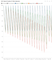
300 minute discharge cycle
discharge of 20 amps and charge of 50 amps.

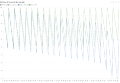
First is SOC over 20 charge/dischage cycles in 15 minute intervals of charge discharge cycles

1716748105200.png


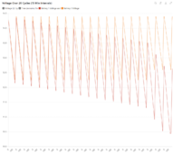
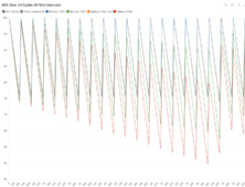
Voltage grap for both batteries over 20 charge/discharge cycles.

1716748361655.png


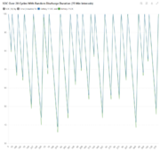
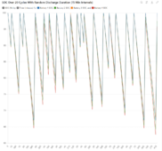
And here is a graph - 2 batteries - random cycle interval from 100 to 400 minutes. It would appear to mean that random cycles over time keep them in sync better than the same repeated cycle.


1716753625353.png
 

Attachments

  • Battery_Cycle_Data__Detailed__20_Cycles_new2.zip
    45.1 KB · Views: 0
Last edited:
Here are the graphs from the same program altered for 4 batteries in series - also the csv file and open document file - Openoffice is freeware

I can expand the number of cycle or adjust any of the variables if you want graphs for your exact setup

Note I am investigating why they start closing up at cycle 17 - wierd - so until I figure it out I am not sure what is going on. I may have to run a hundred cycles or so and see what pops out. I suspect it is interaction when battery 4 goes below 20% and the resistance raises it causes a redistribution.


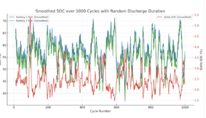
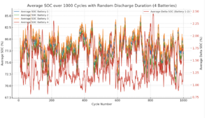
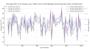
Here is a random duration of discharge - 1000 cycles - 4 batteries -- They stay together pretty well

1716755440951.png


Easier to read version

1716755589872.png


1716755644993.png


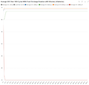
Fixed, one battery crashes and will need a reset - I didn't tell the AI to turn off all others when one dies

1716755851853.png


Because this is a fixed interval for the cycle discharge duration it doesn't represent real world numbers for most people


1716752343038.png

1716752381749.png


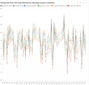
Here is with a random cycle interval between 100 and 400 minutes -- interesting how it changes and keeps the SOC of the batteries together.

1716753284087.png
 

Attachments

  • battery_cycle_data_20_cycles_4_batteries_updated.zip
    59.9 KB · Views: 0
Last edited:
So, interesting outcome from the numbers - numbers don't lie, just people

When the load interval is the same everytime the two batteries drift farther and farther apart until one bottoms out. When the load interval is random the batteries drift apart and back together again with no outside help.

I didn't expect this - So, the equalizer is a way to keep them closer together all the time, but if your usage pattern is random enough you don't actually need the equalizer.


View attachment 217816


I realize this is long - but please sanity check the work and let me know if you see anything I left out.

Once done I'll post the python code and details as a resource for seeing what an imbalance in strings of batteries or cells means.

Included are some graphs of how batteries drift apart and the raw calculations


If they stay together nice and tight that means the internal resistance of the batteries must be almost identical. This is not a given even from batteries that were next to each other on the assembly line.


Assume a charge voltage of 14.4v for a 12.8v battery, 28.8v for 24v battery, 58.4 for a 48v battery

I just measured a 12v LiTime battery at about 95% SOC and it is 2.05mΩ For battery #2 I am assumng 2.15 mΩ


OK, so I spent a few hours getting the AI to return good numbers that pass a sanity check

With a little AI help and giving it some constraints it spits out the deltas over time.
YES! - I know that AI suck at math - they are LLM not SPICE
that is usually when converting units and especially if you don't check the logic of the calcualtions.
And in all cases you have to sanity check all of the output and see if it is in the ballpark of what you expect.
And if it isn't what you expect double check every part of the math - sometime expectations are wrong


Where it gets tricky is the internal resistance varies with state of charge. This means the voltage at the end of a discharge cycle and charge cycle of each battery will be different on each.


Here are the constraints and formulas worked out

### Constraints:
1. **Two Batteries in Series**:
- Each is a LiFePO4 battery.
- Nominal battery voltage is 12.8V (25.6V for the series string).

2. **Initial SOC**:
- Both batteries start at 100% SOC.

3. **Discharge and Charge Parameters**:
- Usage (discharge) is fixed at 300 minutes.
- Battery 1 initial internal resistance: 2.05 mΩ.
- Battery 2 initial internal resistance: 2.15 mΩ.
- Charge voltage: 28.8V.
- Discharge current: 20A.
- Charge current: 50A.
- Discharge and charge cycles step through in 15-minute intervals.

4. **Resistance Based on SOC**:
- For Battery 1:
- SOC < 20%: 3.00 mΩ.
- SOC between 20% and 80%: 1.5 mΩ.
- SOC > 80%: 2.05 mΩ.
- For Battery 2:
- SOC < 20%: 3.15 mΩ.
- SOC between 20% and 80%: 1.65 mΩ.
- SOC > 80%: 2.15 mΩ.

5. **SOC Boundaries**:
- SOC cannot exceed 100%.

6. **Voltage Specifications**:
- Discharge Cutoff Voltage: 10V.
- Float Charge Voltage: 29.2V.
- Nominal Voltage: 25.6V.
- Maximum Voltage: 14.4V (per battery).

### Methods:
1. **Calculate Internal Resistance**:
- For Battery 1:
- \( \text{internal\_resistance} = \begin{cases}
0.00300 \text{ if SOC} < 20\% \\
0.00150 \text{ if SOC} \leq 80\% \\
0.00205 \text{ if SOC} > 80\%
\end{cases}
\)
- For Battery 2:
- \( \text{internal\_resistance} = \begin{cases}
0.00315 \text{ if SOC} < 20\% \\
0.00165 \text{ if SOC} \leq 80\% \\
0.00215 \text{ if SOC} > 80\%
\end{cases}
\)

2. **Calculate Voltage**:
- \( \text{voltage} = \max(10, \min(14.4, \text{nominal\_voltage} - (\text{current} \times \text{internal\_resistance}))) \)

3. **Calculate SOC from Voltage**:
- \( \text{SOC} = \frac{\text{voltage} + (\text{current} \times \text{internal\_resistance})}{\text{nominal\_voltage}} \)

4. **Discharge Phase**:
- Calculate SOC and voltage for each battery independently based on the discharge duration and internal resistance.

5. **Calculate Watts Used**:
- \( \text{Watts Used} = \text{voltage} \times \text{discharge current} \)

6. **Calculate Duration of Discharge**:
- Fixed at 300 minutes.

7. **Charge Phase**:
- Charge both batteries independently until one reaches 100% SOC.
- Stop charging when the first battery reaches 100% SOC, leaving the other battery slightly below 100%.

8. **Calculate Duration of Charge**:
- Calculated based on the difference between SOC at the end of discharge and the target SOC of 100%.

### Formulas:
1. **Internal Resistance Calculation**:
- For Battery 1:
- \( \text{internal\_resistance} = \begin{cases}
0.00300 \text{ if SOC} < 20\% \\
0.00150 \text{ if SOC} \leq 80\% \\
0.00205 \text{ if SOC} > 80\%
\end{cases}
\)
- For Battery 2:
- \( \text{internal\_resistance} = \begin{cases}
0.00315 \text{ if SOC} < 20\% \\
0.00165 \text{ if SOC} \leq 80\% \\
0.00215 \text{ if SOC} > 80\%
\end{cases}
\)

2. **Voltage Calculation**:
- \( \text{voltage} = \max(10, \min(14.4, \text{nominal\_voltage} - (\text{current} \times \text{internal\_resistance}))) \)

3. **SOC Calculation from Voltage**:
- \( \text{SOC} = \frac{\text{voltage} + (\text{current} \times \text{internal\_resistance})}{\text{nominal\_voltage}} \)

4. **Watts Used Calculation**:
- \( \text{Watts Used} = \text{voltage} \times \text{discharge current} \)

5. **Duration of Charge Calculation**:
- \( \text{Duration of Charge (min)} = \left( \frac{\text{capacity (Ah)} \times (\text{SOC\_end} - \text{SOC\_begin})}{\text{charge current}} \right) \times 60 \)

This setup ensures that the simulation accurately reflects the independent behavior of each battery during discharge and charge cycles, considering their specific internal resistances and SOC values. If further adjustments or additional analysis are needed, please let me know.


Here are resulting graphs
300 minute discharge cycle
discharge of 20 amps and charge of 50 amps.

First is SOC over 20 charge/dischage cycles in 15 minute intervals of charge discharge cycles

View attachment 217787


Voltage grap for both batteries over 20 charge/discharge cycles.

View attachment 217791


And here is a graph - 2 batteries - random cycle interval from 100 to 400 minutes. It would appear to mean that random cycles over time keep them in sync better than the same repeated cycle.


View attachment 217810
Just to clarify, the theory that random use will keep things balanced is based on AI/simulations? Or what you saw yourself with your batteries?
 
You'll want a balancer despite the simulation graphs and your Amazon review research.

There are other balancers than the ha01.

Remember to update this thread when you come around.

We won't say told you so.

Does 2big2b mean too big to balance?
 
You'll want a balancer despite the simulation graphs and your Amazon review research.

There are other balancers than the ha01.

Remember to update this thread when you come around.

We won't say told you so.

Does 2big2b mean too big to balance?

Weighing in at 420lbs... I really am "2big2B" or so they tell me ...


And actually, I have just installed a 24v 100ah battery pack with the ha01 balancer in my huge "Big Bounder" power wheelchair. Good to go.
 
Last edited:
Just to clarify, the theory that random use will keep things balanced is based on AI/simulations? Or what you saw yourself with your batteries?


The ai simulation combined with a review of the numbers generated. Now , the random all over the place where I think normal usage in a house power system will be more consistent and therefor need the balancer to keep the batteries in service.

I think I'll alter the program to a random variation off a flattened at the top sine wave to simulate activity in the day so less usage.

I think the program is just a good start at a statistical model of life rather than a complete conclusion.

Sometimes chaos is good and sometimes order is good but to much of either is bad
 
Back
Top