paulca
New Member
- Joined
- Sep 13, 2022
- Messages
- 77
How to repair a Growatt SP2000.
DISCLAIMER: This worked for my SP2000, which had a PV Short Circuit fault , it may not work for yours. but, having said that if one of your IGBT’s is blown, it’s probably the cause of your issue, and it’s relatively simple to test; a bit more complex to fix.
Before attempting to dismantle the unit ensure you've followed the official shutdown procedure and have disconnected the PV, INVERTER, AC and BATTERY from the unit. THERE MUST BE NO CONNECTIONS to the unit.
If you have any unused/damaged growatt kit you no longer need, please PM me. I'm researching different faults on these units and hope to write a 'how-to' repair guide for any I can get my hands on.
If you've got a shorted one , or open circuit one, move onto REMOVAL below.
DISCLAIMER: This worked for my SP2000, which had a PV Short Circuit fault , it may not work for yours. but, having said that if one of your IGBT’s is blown, it’s probably the cause of your issue, and it’s relatively simple to test; a bit more complex to fix.
Before attempting to dismantle the unit ensure you've followed the official shutdown procedure and have disconnected the PV, INVERTER, AC and BATTERY from the unit. THERE MUST BE NO CONNECTIONS to the unit.
If you have any unused/damaged growatt kit you no longer need, please PM me. I'm researching different faults on these units and hope to write a 'how-to' repair guide for any I can get my hands on.
- Tools required : Philips screwdriver , Torx T15 screwdriver, Multimeter, pliers, soldering iron, solder, de-solderer

- Get an empty egg box to put your screws in, work top left to bottom right, like reading a book.
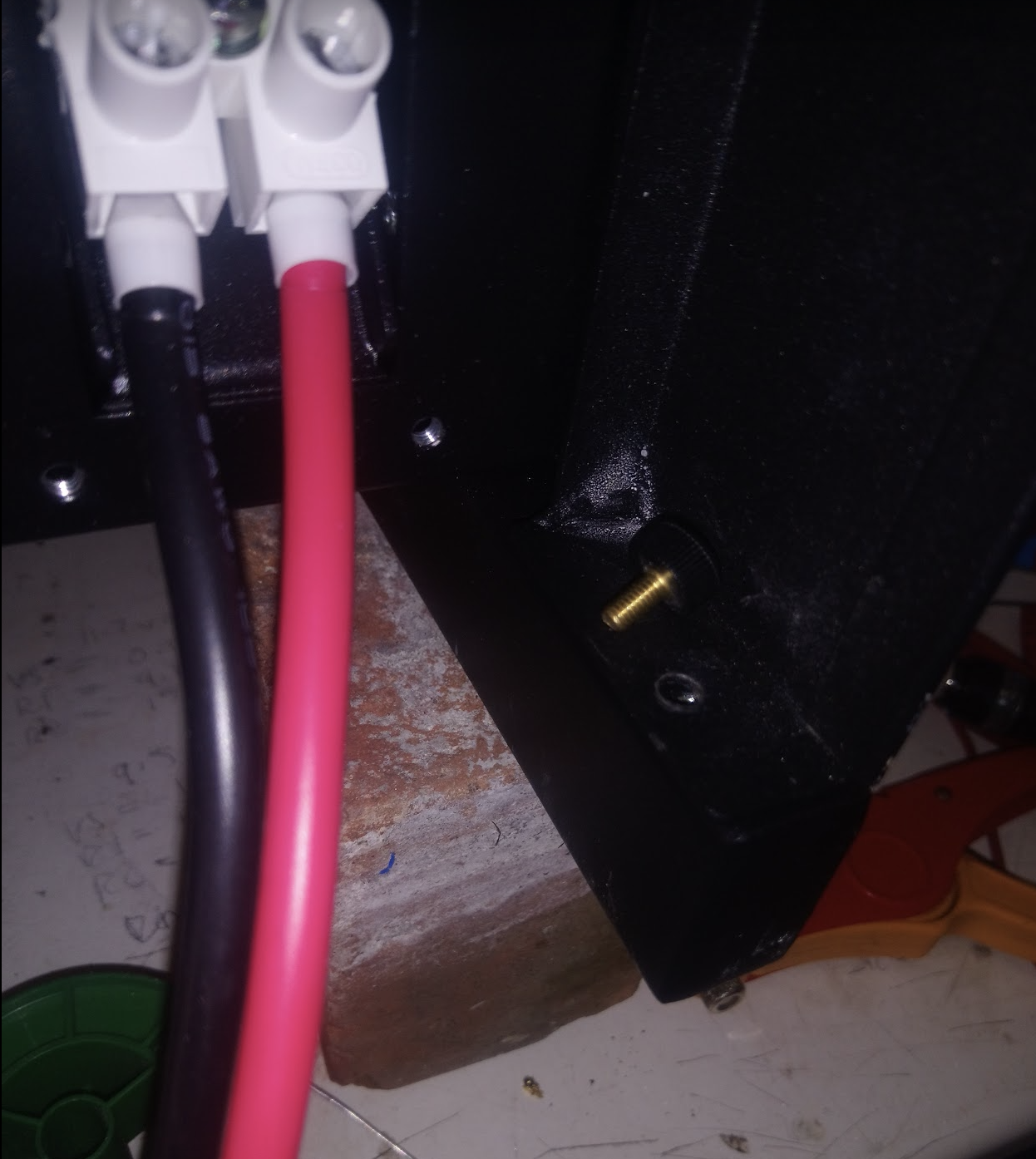
- Remove the 2 thumb/butterfly screws holding the black steel shroud that surrounds the base of the unit Put the screws into egg 1 position (top left of the egg box). The shroud comes off by sliding it sideways , then pulling out.
- Using the torx screwdriver remove the 8 screws that hold the face on, 3 top, 2 sides, 3 bottom. Also stick them in egg 1 position.
- Remove the face by lifting straight off.
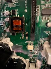
- Now it looks a bit terrifying with the face removed, but don’t panic, you’re now only a few screws away from testing the IGBT’s


- Remove the 3 screws holding the green LED board in place, disconnect the ribbon cable by gently pushing the 2 retaining lugs outwards….screws in egg box 2....place the LED board to one side.
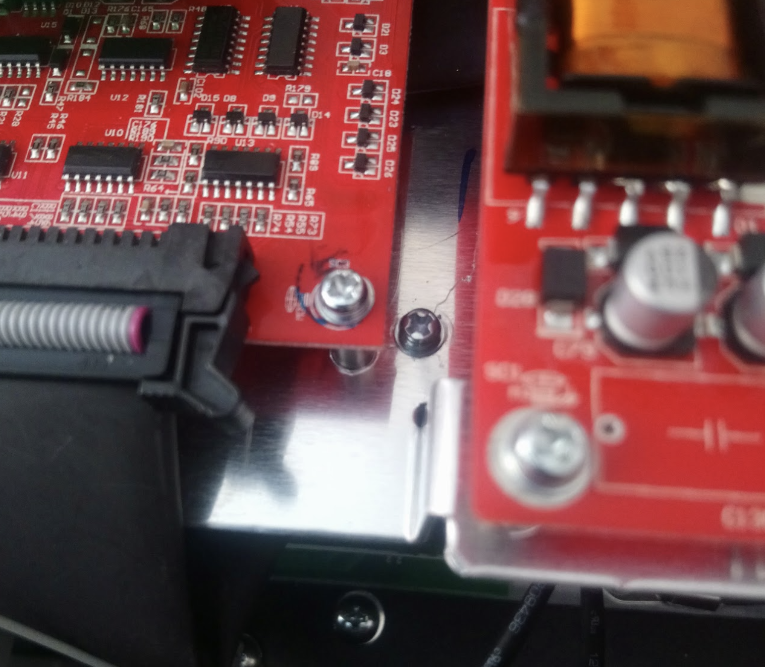
- Next, remove the 6 screws securing the aluminium mounting plate for the daughter boards. Theres 2 left 2 right which are obvious, and 2 in the middle between the red boards which aren’t immediately obvious….screws in egg box 3
- You need to disconnect the 2 ribbon cables on the top and bottom of the left red board in the above pic, then the whole assembly should lift out. I was lazy and just left the other connections on the right board attached and let it dangle in front of the unit, but if you're less lazy you can disconnect them, just take a photo before you do so you know which connector goes where.
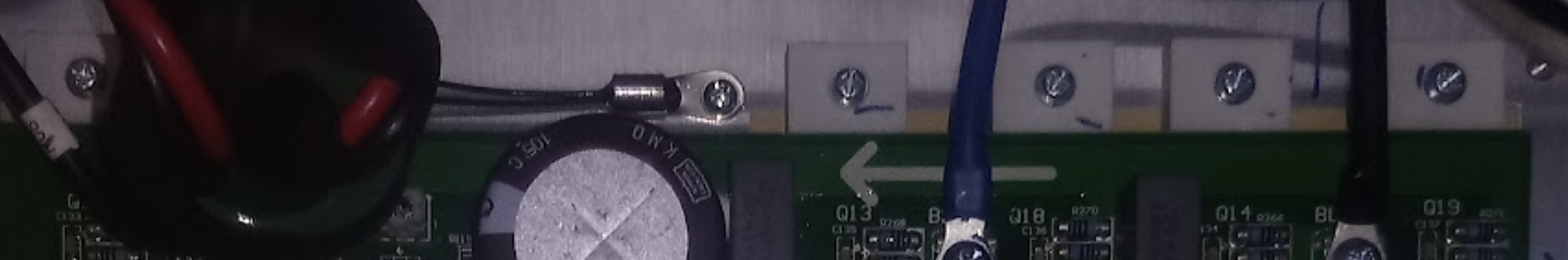
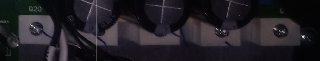
- NOW you can see all the transistors, there’s 11 of them in total, and 2 different types, but the testing procedure is the same for each.The high power transistors run around the top and bottom right edges of the mainboard. Each transistor has a white plastic block securing it to the heatsink at the back.
TOP ones (6 of)
BOTTOM ones (5 of)
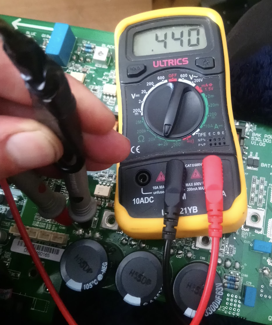
- Each transistor has 3 solder connectors on the board, marked G,_,E top row, G _ S bottom. Put the multimeter on diode setting, and place it across the S/E and the middle pins with the red on the S as shown below. The board may be varnished,so push hard. You should get a reading of roughly .440 and the top ones should be .390 ish.
If you've got a shorted one , or open circuit one, move onto REMOVAL below.
Last edited:


") .
.