Johan
Off-grid energy systems enthusiast.
Calculation model description
This thread focuses on the calculation of an approximate estimation of the maximum C-rate for a given battery and/or the cell temperature (increase) at full (dis)charge for a given C-rate.
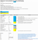
It is conservatively assumed that heat cannot escape from the battery. Hence, all generated heat will contribute to a rise in the battery temperature. The calculation model only applies to a single full charge (or discharge), after which it is assumed that the battery is allowed to reach thermal equilibrium with the ambient temperature. Attached is an Excel-sheet (see also screenshot below) with the appropriate assumptions, in- and output fields, and equation derivations. The approach is extremely simple so you can easily check it yourself. You can enter your own battery specs.
Example
Given a CALB 3.2Vnom 180Ah LFP cell of 5.6kg with a 0.6mΩ internal resistance, 20°C ambient start temperature and 55°C maximum internal temperature, the maximum theoretical C-rate would be roughly 1.6 until the maximum internal temperature is reached. At a C-rate of 1, approximately 3.4% of the battery capacity would be lost as heat, roughly matching an earlier design statement that @electric made here.
Discussion
Note that factors other than the cell internal temperature may limit the maximum C-rate as well, but these are not identified nor discussed here. Hot spots and consecutive continuous cycling (etc) are neglected, suggesting an over-estimation of the max C-rate. On the other hand, in practice, heat can always escape because a perfect adiabatic condition is impossible. In this regard, the calculation model predicts an under-estimation of the max C-rate. These systematic errors may partially cancel each other out . Large uncertainties apply to the battery internal resistance, i.e. a factor 2 increase would reduce the modeled max C-rate by a factor 2. Note that cycle life degradation as a function of internal temperature is not addressed. Experimental validation of this model is lacking from my side. However, the model does suggest that (dis)charging at "fractional C-rates" (0 to 1C) would not lead to heating problems as @electric already suggested (again) here, provided that the ambient temperature is low enough. I am curious what improvements y'all propose for this calculation model.
I will try to process comments from below into the sheet and update it in this message.
Edit: When the cell specsheet only mentions an "impedance", then you could simply multiply that impedance by a factor 2 (or 4) to obtain a rough conservative estimation of the DC internal resistance for most (?)(not all) cells. I loosely base this statement on the following graph: http://liionbms.com/php/wp_resistance_vs_impedance.php
Screenshot (example of older version)

This thread focuses on the calculation of an approximate estimation of the maximum C-rate for a given battery and/or the cell temperature (increase) at full (dis)charge for a given C-rate.
It is conservatively assumed that heat cannot escape from the battery. Hence, all generated heat will contribute to a rise in the battery temperature. The calculation model only applies to a single full charge (or discharge), after which it is assumed that the battery is allowed to reach thermal equilibrium with the ambient temperature. Attached is an Excel-sheet (see also screenshot below) with the appropriate assumptions, in- and output fields, and equation derivations. The approach is extremely simple so you can easily check it yourself. You can enter your own battery specs.
Example
Given a CALB 3.2Vnom 180Ah LFP cell of 5.6kg with a 0.6mΩ internal resistance, 20°C ambient start temperature and 55°C maximum internal temperature, the maximum theoretical C-rate would be roughly 1.6 until the maximum internal temperature is reached. At a C-rate of 1, approximately 3.4% of the battery capacity would be lost as heat, roughly matching an earlier design statement that @electric made here.
Discussion
Note that factors other than the cell internal temperature may limit the maximum C-rate as well, but these are not identified nor discussed here. Hot spots and consecutive continuous cycling (etc) are neglected, suggesting an over-estimation of the max C-rate. On the other hand, in practice, heat can always escape because a perfect adiabatic condition is impossible. In this regard, the calculation model predicts an under-estimation of the max C-rate. These systematic errors may partially cancel each other out
I will try to process comments from below into the sheet and update it in this message.
Edit: When the cell specsheet only mentions an "impedance", then you could simply multiply that impedance by a factor 2 (or 4) to obtain a rough conservative estimation of the DC internal resistance for most (?)(not all) cells. I loosely base this statement on the following graph: http://liionbms.com/php/wp_resistance_vs_impedance.php
Screenshot (example of older version)

Attachments
Last edited:


