cliffstevens
New Member
I have begun exploring a solar system for my small 1930s home in Arlington VA. I'm not sure yet about how many panels I can fit on my roof, and will certainly figure that out by talking to some solar installers, but right now I think only 25 or so panels, maybe 30 (of course depending on size). I have a good southern facing high up area of the roof, with minimal shade during most of the day. But I'm guessing right now I can only generate half of our monthly power needs of about 2000 kWh/hours a month towards the higher end in summer. I also want battery backup for the not infrequent storms in our area that often take out the strung power lines (from all the old trees).
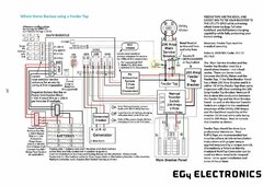
My question is - if I was able to get a system like the EG4 18PVK and a couple of "matching" EG4 wall mount batteries installed, would AC passthrough from the grid supply all of the power I need that the solar system/batteries cannot produce at a given time through the inverter? So the inverter in the EG4 18 PVK is 12,000 watts continuous (with surge above that for some amount of time), or something like that. What if I need 20,000 watts at some time? I'm a total beginner and not sure if I have a load like that in my home, and will find out (maybe by installing an Emporia or something similar). But just from a system design standpoint, if I knew that the 18PVK could always draw from grid over 12000 watts and supplement that, then that is really helpful and makes designing the system a lot easier. I can only produce so much solar power, and probably not enough for our total needs. So we are going to be drawing from the grid no matter what. It would be nice if the AC added on top of the inverter capacity, rather than for example the load only running off the inverter or the grid, and not both at the same time
So here's my question. How does AC passthrough from the grid work on a system like this? Does it draw as much load as it can from the solar DC coming in and battery (up to the inverter capacity) and then add more AC load on top of that? Or can the 18PVK only supply 12000 watts AC (with whatever surge), even from the grid? If it worked that way, they maybe I'd need multiple 18PVK. I hope they don't work that way, but I don't know.
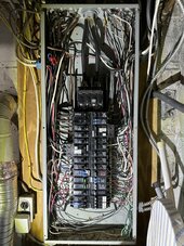
Also, I think I have a 200 amp grid line coming in. Obviously I"m going to be learning a lot more about my house electrical system, but I am a real beginner on this.
Thanks for any help.
My question is - if I was able to get a system like the EG4 18PVK and a couple of "matching" EG4 wall mount batteries installed, would AC passthrough from the grid supply all of the power I need that the solar system/batteries cannot produce at a given time through the inverter? So the inverter in the EG4 18 PVK is 12,000 watts continuous (with surge above that for some amount of time), or something like that. What if I need 20,000 watts at some time? I'm a total beginner and not sure if I have a load like that in my home, and will find out (maybe by installing an Emporia or something similar). But just from a system design standpoint, if I knew that the 18PVK could always draw from grid over 12000 watts and supplement that, then that is really helpful and makes designing the system a lot easier. I can only produce so much solar power, and probably not enough for our total needs. So we are going to be drawing from the grid no matter what. It would be nice if the AC added on top of the inverter capacity, rather than for example the load only running off the inverter or the grid, and not both at the same time
So here's my question. How does AC passthrough from the grid work on a system like this? Does it draw as much load as it can from the solar DC coming in and battery (up to the inverter capacity) and then add more AC load on top of that? Or can the 18PVK only supply 12000 watts AC (with whatever surge), even from the grid? If it worked that way, they maybe I'd need multiple 18PVK. I hope they don't work that way, but I don't know.
Also, I think I have a 200 amp grid line coming in. Obviously I"m going to be learning a lot more about my house electrical system, but I am a real beginner on this.
Thanks for any help.
Last edited: