diy solar

diy solar

new installation, they say my inverter is bad

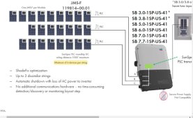
Be sure to know how many RSD's are required per string. SMA RSD's require a minimum of 6, max is 30. Tigo told me 7 is min. AP Systems may be different also. That little detail almost derailed my install...

fwiw - I decided to kiss and use all SMA, inverter and RSD. Some of those transmitters are only warrantied 5 or 10 years. SMA RSD have a 25 yr warranty.
What triggers the minimum number of RSD?

Do you have a reference to this in the manual or specs?

EDIT: I understand that the maximum comes because they tend to buck down to a standby voltage to provide standby power to the string inverter, and 30V or 30*1V hits the NEC voltage limit outside the array boundary. The minimum, is that to comply with a sunspec standard for minimum string voltage to bootstrap string inverter?


Yes. And emailed SMA to confirm. I orginaly found that 6 RSD requirement per string in an SMA RSD brochure. It was worded something like "RSD outputs 1 volt.... a couple sentences later..... Sunspec/Rapid Shutdown (cant remember the exact words) requires 6 volts". I read it 10 times with a couple wtf's. Then looked closely at the spec sheet and saw this:

"Allowable series string connections: 6 to 30 JMS-F devices"

https://files.sma.de/downloads/SMASunSpecRSD-DS-en-21.pdf


Here is SMA's response to the email asking about number of RSD's required per string:

"Thank you for your email. The RSD will need to have at least (1) string of (6) PV modules."


Like I said, that detail almost derailed my system which prompted me to call Tigo regarding their RSD. Same with AP Sytem RSD requirements.
 
Last edited:
Yes. And emailed SMA to confirm. I orginaly found that 6 RSD requirement per string in an SMA RSD brochure. It was worded something like "RSD outputs 1 volt.... a couple sentences later..... Sunspec requires 6 volts". I read it 10 times with a couple wtf's. Then looked closely at the spec sheet and saw this:

"Allowable series string connections: 6 to 30 JMS-F devices"

https://files.sma.de/downloads/SMASunSpecRSD-DS-en-21.pdf


Like I said, that detail almost derailed my system which prompted me to call Tigo regarding their RSD. Same with AP Sytem RSD requirements.
Hmm, I'm not sure what you can do about this though besides checking all the spec sheets to find the one that fits the geometry you need. If the minimum is determined by my theory re: the standby voltage level, then it follows that if you choose a system with a low minimum device count. This has the consequence of a lower max device count, but I guess 30s is anyway not legal to install in resi anyway (*)

EG suppose standby voltage is 2V and it is not adjustable. NEC says the limit is 30V

Sunspec minimum = 6V, so minimum string is 3s. Maximum string is then 15s.


Note in that SMA specsheet it says the standby voltage is 1V

I'm pretty sure it's going to be covered in here, with 2 min of searching I see some references to minimum standby voltage/current needing to be high enough to power monitoring when the system is shut down.

My use case for RSD is slightly off label so I'm not concerned/don't think I want to proactively dig into this further.

But for standard string inverter use case it may affect code compliance / functionality. This will require a careful reading of the instructions and specs of the specific string inverter.

(*) Now maybe they should offer a higher standby voltage RSD for residential... Currently the lowest VOC resi panel is 54 cell with 34 VOC. 600 / 34 17s maximum allowed in residential to stay under 600V NEC limit. 6/(30/17) = 4s minimum string size, slightly better than 6s and 7s that you quoted above.
 
How did the SMA RSDs fix the system? Are they allowed to deviate from SunSpec when used with a pure SMA system?

If that is the out you gave yourself to allow shorter strings, what happens if SMA implodes, no replacements available, and you need to go to a SunSpec string inverter from a different company?
 
How did the SMA RSDs fix the system? Are they allowed to deviate from SunSpec when used with a pure SMA system?

If that is the out you gave yourself to allow shorter strings, what happens if SMA implodes and you need to go to a SunSpec string inverter?


Can not and did not deviate. However, when I emailed SMA regarding RSD's I did ask if its possible to put two RSD's in series - use 5 panels with 6 RSD's. They ignored that question most likely thinking "that guy is an idiot". lol

Solution was to first met with the building department, prior to plan submission, explaining the roof layout with 6 panels in regards to fire dept setbacks and hips. They were fine with not having 18" setbacks on both roof hips, both sides of the 6 panel array. After that hurdle I then moved a bathroom roof vent that was in the middle of the array. Permits were approved last week:))) And ordered SMA RSD's today.
 
OK, that is a smart solution,

LOL, 5 panels with 6 RSDs is creative but probably not going to work, unless the RSDs use floating buck topology to buck down to 1V (and then you can get 2V from a single panel by doubling up). Those extra components probably just add cost / things to fail and are useless except for this edge case.

Theoretically the TIGO RSD+Optimizer (non-Sunspec I believe since they are RF controlled) could buck down to a higher standby voltage as needed, since at least 50% of the optimizer is nothing but a variable buck converter with 33% matching capability, and this matching capability is sufficient to push some panel types below 30V. That gets kind of complicated though.
 
Hello everyone, I wanted to give an update after having to go round and round to get this system working.
It did end up being the rapid shutdown modules. The inverter that I have isn't compatible and/or doesn't send the "wake up" signal needed by the RSD modules. I asked the installers and they acted dumb. I am beginning to thing they are, or just asses.
Anyway, I ordered the APsmart – Single Core Transmitter PLC Outdoor Kit and installed it myself. It works. I have a working system now.

Oh, BTW, would the system sitting in shutdown for almost two months fry the shutdown modules? I think I have 3 panels that are not producing because of that. The max output is 4.5kw when before it was right at or more than 6kw.
Also, if I have string with 12 panels and a second string with 8, then the string with 12 should have a higher voltage/amperage, right?
That's why I think there are some that are not working.
 
I do have one more thing to ask you all.... on my setup/house, there are two banks of panels. 12 on the front of the house that gets AM sun, 8 on the carport that gets afternoon sun. Would it be normal to have those two strings wired in as front and back, or should they have wired it mixed? (inverter has two string inputs) Meaning, each string has some panels from front and back in it to "balance" things?
 
No balancing is actually actively bad and ruins production.

Unless you have the highest end type of solar optimizers (MPPT style, not TIGO style), or microinverters, you do not want to mix strings like that. Every roof plane should be on the same MPPT. All solar panels in the string should be matched.

It is OK however to have the total DC size of the system be larger than the AC output rating of the inverter, since the front and back of the house will see peak production at different times.
 
Greeeaaaaaaattt. Another strike on this company.
So if there are two red and two black wires going to the front, then it probably is mixed, right?
I mean, if it's a simple DC system, then one red and one black (plus ground) should be all that is going to the front bank. Same for the carport.
With all that said, I am going to have another company inspect this and see what the heck can be done to correct this. I hope a re-wire doesn't have to happen, but mentally that is what I am preparing for.
 
another update.....
so i did have another company come out and perform an eval of the system. they found that they did wire a "mixed" type setup.
there is 10 panels on each string, but 2 of the front 12 are on the back string. ( i am still hoping to get the eng plans for more details )
it seems that if they did all 12 on one string, then it would have been too much input voltage during cold weather, hence the split of 10 each.
is that ideal? i do not think so, but hey, what do i know?
for now, I am just going to run it as-is and plan to upgrade the inverter, which admittedly is considered "old" by modern system standards, and then add a panel or two to the back string, while moving one or both to the front string if the invertor can handle it.
this has been an educational process to say the least and as the other company i had look at things has said, "this industry if full of people taking advantage of people." that's any industry, but this one more so.
 
Back
Top