The unit from LTT given in the above post should arrive quickly as they send air mail. Its the same as sold by Overkill but without the cable options that Overkill offer.
From,
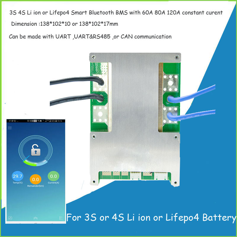
1) Application:this smart BMS can work for 3 to 4S Lithium ion or Lifepo4 Battery ,client can choose based on your battery chemistry features 2) Current : constant current of this version BMS can be made with 40A to 120A in accoridng to the different demand 3) Dimension: :Max 138*102*15mm for...

www.lithiumbatterypcb.com
You can pay with Paypal, shipping to the UK was 6 days.
Regarding the issues you are having, you may have already carried out the following but this is the method I used.
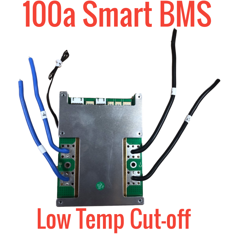
Withe the balance leads disconnected from the BMS connect to the cells taking care the white leads are in the correct order.
Connect the blue power cables to the battery negative, then connect the balance connector to the BMS.
If any work is carried out on the battery or leads to the BMS, the balance connector must be unplugged first.
If the sequence is not followed there is a possibility of damage to the BMS.
The voltage readings are way off for cells 1, too low, and 3, too high. Have you confirmed that these are the actual voltages with a meter?
If cell 3 actually has a voltage over 14 volts it may be damaged and needs discharging to a safe level.
Mike