diy solar

diy solar

Solar panels transmitting their own signal into space

drjaymz

New Member
Joined
Apr 18, 2024
Messages
13
Location
Uk
I have noticed some pretty large interferance coming from the panels themselves. Now I know that panels radiating switching noise based on their converter isn't uncommon and there are ferrite chokes to deal with that if it becomes a problem.

For me though I'm getting interferance radiating at 50Hz (or 100hz)
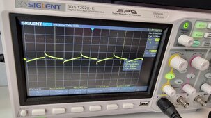
1715007819760.jpeg

I'm using an easun 3.2kw hybrid. The pure sine output has a little HF noise on it but honestly not too bad.
I first noticed the effect with microphones picking up a mains buzz. I thought maybe there was some ground loop issue so made sure the ground was correct all tied to the common point.

So normally if you place your finger on the scope input you'll couple some 50z into it from ring mains etc. But I am seeing pretty large square wave peaks.
It took me a while to pinpoint this but I can now see that its the solar array itself. In my office the roof has 6 panels and they are connected in series which means there's effectively a loop. So at 8A which they are running at thats an air cored electromagnet pointed at my head, but its DC.

I'm not sure how the actual inverter is designed or coupled to the PV input but it looks like the entire array is acting like one plate of a giant capacitor whose polarity switches when the AC mains is crossing zero or maybe at peak. I don't think ferrites are going to cure this.
To prove that its the array I can switch the main isolator, no difference, I can go into grid bypass mode, no difference and then finally switch the panel isolator and then it goes away completely.

I don't think its faulty I think its to do with the way the PV is switched into the DC bus in the inverter.

Has anyone else seen this? I'm guessing it just doesn't bother anyone else and people just assume the inverter is noisy which oddly it isn't its pretty well behaved.
 
I don't think its faulty I think its to do with the way the PV is switched into the DC bus in the inverter.
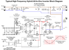
More precisely it has to do with how DC bus is switched into grid neutral via low frequency H-bridge IGBTs. It causes PV terminals to be biased at 50hz by DC bus voltage in relation to neutral and earth ground. This is normal operation inherent in this non-isolated Voltronic type inverter design. Analyze this schematic to see what's happening.

hybrid inverter schematic3.png
 
More precisely it has to do with how DC bus is switched into grid neutral via low frequency H-bridge IGBTs. It causes PV terminals to be biased at 50hz by DC bus voltage in relation to neutral and earth ground. This is normal operation inherent in this non-isolated Voltronic type inverter design. Analyze this schematic to see what's happening.

View attachment 213651
Awesome I'll have a look good look at that.
 
More precisely it has to do with how DC bus is switched into grid neutral via low frequency H-bridge IGBTs. It causes PV terminals to be biased at 50hz by DC bus voltage in relation to neutral and earth ground. This is normal operation inherent in this non-isolated Voltronic type inverter design. Analyze this schematic to see what's happening.

View attachment 213651
Yes, simple enough and pretty much what I thought it would be doing. I can see that its pushing then pulling against Neutral depending on which half of the cycle its on. I guess you can't do much about it unless you galvanically isolate it. Thing is that square waves create the worst EMI. So this is causing the 50hz square electric field in my office which isn't really a problem and I haven't noticed much effect on SDR setup.
 
More precisely it has to do with how DC bus is switched into grid neutral via low frequency H-bridge IGBTs. It causes PV terminals to be biased at 50hz by DC bus voltage in relation to neutral and earth ground. This is normal operation inherent in this non-isolated Voltronic type inverter design. Analyze this schematic to see what's happening.

View attachment 213651
Found your problem, some idiot forgot to install a transformer and hooked your mains right to the driver circuit. Probably trying to save a buck on copper....
 
Here is RFI mitigation thread from a month ago.
Thanks. He has hf noise from the inverter and by the sounds of it he has ground loops. I irradicated ground loops early on. I expected more hf noise from the inverter but its not too bad appears to be reasonably filtered. Its the low frequency square switching wave which no amount of chokes will remove, they might take the edges off and reduce hf components but not much you can do. What I need to do is have a groundplane below the panels they can capacitively couple with although I thought my roof had foil insulation in it which may make it worse.
 
Unless you are listening to VLF nuclear submarine signals then 50 Hz should not be an issue. Ferrite chokes block RFI above 100kHz pretty well.
 
Unless you are listening to VLF nuclear submarine signals then 50 Hz should not be an issue. Ferrite chokes block RFI above 100kHz pretty well.
I would not have noticed it except for two things. 1) loud audio buzz being picked up by a webcam, others were fine. 2) I have a ultrawide monitor that seems to be sensitive to interferance that likes to to randomly display black. I changed it from 60 to 120Hz ins it now doesn't randomnly resync. If you tear the cover off the easun it already has a fair bit of filtering in fact probably 30% of it by weight is filtering. I could add some chokes to the PV leads which will attenuate 100khz+ but not having too much issue with that and the 50hz fundamental will still be there. It is fine now that I have looked at the schematic its inherent in the design. Its only because I'm close to the panels may be 1m above my head that it was picked up. On top of a house it would not bother anyone, there are plenty of stray 50hz signals coming from the mains.

It did open my eyes however to the fact that solar panels with their large areas and cable runs could easily be a EMC nightmare for HAM radio. One issue is that its tricky to control by the design of the inverter, every installation is different and one might radiate a lot where another very little.
I do use an SDR scanner and didn't really notice any effect in the bands I am scanning but lower HF might be much worse.
 
My first thought was RSD keep-alive. My second thought was MPPT switching frequency. Hams hate optimizers and microinverters but those would be out of sync with each other.
 
I found my Schneider's ferrite chokes the other day in the accessory bag, with the clear instructions to install them. I need to get around to that.
I put the choke on today. I just put the PV +/- through the ferrite, it's the collar shape rather than the ring shape. @AntronX Should I actually be doing any wrapping around the choke? I didn't think of that until I read this thread's updates this morning.

It's a standalone DC charge controller, so no AIO type interference. Grid charger and the inverter probably still bring some of their own high frequencies onto the DC bus though.
Yes you want at least one turn, further turns will make it more effective - its doesn't stop EMI it just attenuates it. The inverter should already have some supression. The thing about these is that you really have to measure it before and after to know what you need and how well its working. This is what I mean about no two installations being the same. You could be unlucky and have cable runs that emit really well and others where the length or routing prevents it radiating and it would also seem that it can change depending on the storage charge state and the amount of sunlight and just keep shifting around all day so I don't see how any piece of equipment can really be certified in isolation.

Anyway in my case it was low frequency buzz and can't attenuate that anyway.
 
I'm not sure how the actual inverter is designed or coupled to the PV input but it looks like the entire array is acting like one plate of a giant capacitor whose polarity switches when the AC mains is crossing zero or maybe at peak.
You are exactly right. It is like a giant capacitor, but the way it works is the whole array potential is shifted up and down on every AC cycle.

There are a number of designs, the most popular uses 5 switches if I remember correctly. Another one with 7 is described here https://www.mdpi.com/2071-1050/15/10/8405

The way a modern inverter works(greatly simplifying) is it connects the panels with a combination of capacitors used to boost the voltage directly to the grid (either DC+ to Line and DC - to neutral on the positive part of the cycle, or DC to line and DC+ to neutral on the negative side) for very brief periods of time. As a result if you connected an oscilloscope referenced to ground to your DC+ or DC- you would see AC superimposed on both (perhaps doubled). I dont recommend this experiment as most scopes can't take such voltages. The fact electrodes shift so far potential wise compared with surrounding air(especially in moist environment) is even detrimenal to certain types of panels that can't be used with such inverters due to pid. I researched this a lot to make pid-susceptible panels work with such inverter.

I don't think its faulty I think its to do with the way the PV is switched into the DC bus in the inverter.

Has anyone else seen this? I'm guessing it just doesn't bother anyone else and people just assume the inverter is noisy which oddly it isn't its pretty well behaved.

Yes, I'm a ham radio operator. I currently have just 2.4kW, but I'm looking for at least 16kW more so I'll be looking for methods to stop this Emi.
 
You are exactly right. It is like a giant capacitor, but the way it works is the whole array potential is shifted up and down on every AC cycle.

There are a number of designs, the most popular uses 5 switches if I remember correctly. Another one with 7 is described here https://www.mdpi.com/2071-1050/15/10/8405

The way a modern inverter works(greatly simplifying) is it connects the panels with a combination of capacitors used to boost the voltage directly to the grid (either DC+ to Line and DC - to neutral on the positive part of the cycle, or DC to line and DC+ to neutral on the negative side) for very brief periods of time. As a result if you connected an oscilloscope referenced to ground to your DC+ or DC- you would see AC superimposed on both (perhaps doubled). I dont recommend this experiment as most scopes can't take such voltages. The fact electrodes shift so far potential wise compared with surrounding air(especially in moist environment) is even detrimenal to certain types of panels that can't be used with such inverters due to pid. I researched this a lot to make pid-susceptible panels work with such inverter.


Yes, I'm a ham radio operator. I currently have just 2.4kW, but I'm looking for at least 16kW more so I'll be looking for methods to stop this Emi.
I measured pv- and pv+ with respect to earth and I get 16VAC which is a ringing square wave. Now earth is tied to neutral so its not quite as shown in the above diagram I think the pv boost converter is actually a transformer not a simple inductor arrangement and it seems isolated to some degree. But there's some weak capacitive coupling.
 
Back
Top