diy solar

diy solar

Starting a Parts Library & Using FreeCAD as a Design Tool

Symbioquine

Solar Enthusiast
Joined
Jul 6, 2021
Messages
432
Hi Folks!

I've been playing with various off-grid systems for a while now, but just starting to get into building my first LiFePO4 system.

With any building/design project, one thing that really helps me think through the spatial and material requirements is being able
to visually assemble the system before I've cut/fastened/bought any parts. For this, a CAD program is ideal - and being an Open Source
fan, FreeCAD is the flavour of choice for me.

This is a bit of a multi-pronged thread. I want it to;
  • Start a discussion where folks can share their experiences with Open Source CAD software as a DIY Solar/Energy system design tool. Perhaps those who've had successes can also share screenshots/renders of their finished models to inspire others.
  • Solicit ideas for the best way to maintain a community parts library resource. Many companies already provide CAD files for their hardware so these could simply be linked, but other hardware has to be modeled from scratch. My thought is that if we can share low/medium fidelity models of common specific hardware and generic things like breakers/busbars/etc these can reduce the time/effort needed to generate useful 3D system design documents.
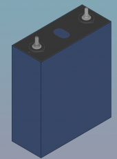
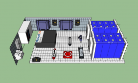
I'll kick things off with a screenshot of how I'm thinking of laying out my new system and a model of the Eve LF280K battery that I made.
(Obviously, don't blindly trust the dimensions I've used in the model. I've done my best to follow the spec. sheet, but I could have made
errors or your cells could be different.)

Cheers,
Symbioquine
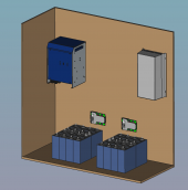
1628266654942.png1628266931687.png
 

Attachments

  • LF280K.FCStd.zip
    661.3 KB · Views: 16
...one thing that really helps me think through the spatial and material requirements is being able to visually assemble the system before I've cut/fastened/bought any parts...
I love this sentiment! I see too many people that bought from the "incredible sale" and then got stuck with stuff because there wasn't a plan.

That includes me. I bought my first cells with only the roughest idea of what I was going to do... it wasn't until I was going to steal parts off an old dead jump-starter I started going hmmmm. Even though it was just a small test project, have to admit it's been very useful.

Might want to look at adding some wheels to yours for portability! Take a look at some of the hand-cart builds in the show & tell forums.
 
Might want to look at adding some wheels to yours for portability! Take a look at some of the hand-cart builds in the show & tell forums.

Definitely applicable to some builds, but probably not this one...

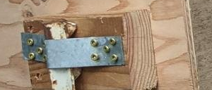
IRL that cabinet is a 48"x48"x20" plywood box with some 2x4 structure on the outside. It's mounted to recycled fencing T-posts driven into the ground with pieces of structural metal strapping.

1628299699871.png

I just didn't model the box in much detail since the part I'm focusing on now is the layout of the stuff that goes inside.
 
Do you have a compression and fire strategy? (Never considered those in my build and don't plan to retrofit them (although a few more fire threads and I might), but curious what others are doing for my "next" build).
 
Do you have a compression and fire strategy?

For compression I'll probably go with the plywood and threaded rod strategy, but I haven't gotten there in my design yet.

Wasn't planning on an active fire strategy other than a super canonical build using Grade A LiFePO4 cells from Shenzhen Luyuan Tech. Co. + right-sized wire/fuses + clean crimps and cable management. (Tell me if that's naive...)
 
I drew the heck out of my design before I bought anything. I new ahead of time exactly how my batteries were going to fit. The CAD program (Sketchup) that I used let me know that my original location for the batteries wasn't going to work. Once I had all the dimensions of my components, I knew down to the inch where everything was going to be placed.

The only thing the CAD program couldn't help with was cables. How tight of a bend could I put on a cable? I had no idea and I did end up with a design that was a little too tight on tolerances for cabling. Some of my cables just barely squeaked into where they had to go.

I found some stock components that helped me out. But I still had to create a few too.

1628353279264.png
 
...Tell me if that's naive...
No clue really. I think it depends on the size. I've been thinking more on it with the recent threads where people's systems have caught fire. I don't know that one cell going up is all that catastrophic, but with heat through the bus bar when one goes it takes out its neighbors who take out their neighbors, etc.

For example, the Jump Start I built is 400 watt hours, and my "basic" fire plan is to scoop it up on a shovel and drop it on the driveway until it burns itself out.

I have ~13 kWh on the side of my house, but it's not DIY and UL listed. If it caught fire I could kill the power and it's bolted to a concrete wall. It's LFP and not supposed to catch fire easily, but the fire temperature of LFP is 518°F, and concrete is damaged over 500°F. That would be an expensive repair. Hmmm, I guess I should move the gasoline storage from the other side of that wall to somewhere else.
 
The only thing the CAD program couldn't help with was cables. How tight of a bend could I put on a cable? I had no idea and I did end up with a design that was a little too tight on tolerances for cabling. Some of my cables just barely squeaked into where they had to go.

This is actually one of the aspects I haven't figured out either. It seems like it should be easy to model cables both for visual/layout design purposes and to determine whether bends/clearances are going to work out.

Unfortunately, it doesn't seem like there's a very good way to do this in FreeCAD. The best I've found for 3D wire routing is creating a path from multiple sketch lines - where each sketch only curves in two dimensions.

The Draft workbench also supports 3D "wires" either as a sequence of line-segments or as a bézier curve, but the editing experience for those primitives was incredibly clunky to the point where it just felt like a waste of time.

No clue really. I think it depends on the size. I've been thinking more on it with the recent threads where people's systems have caught fire. I don't know that one cell going up is all that catastrophic, but with heat through the bus bar when one goes it takes out its neighbors who take out their neighbors, etc.

I guess right now I'm leaning towards trusting the tentative conclusion in this thread: https://diysolarforum.com/threads/can-lifepo4-batteries-combust-in-thermal-runaway-event.999/
 
1669489444814.png

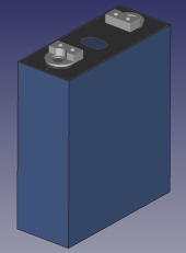
Attached is an updated EVE LF280K model with the new terminal style. Both FreeCAD and Step file formats are included in the zip archive.

The terminal geometry itself is copied from @Ron-ski's model on https://diysolarforum.com/threads/sketchup-drawing-of-new-eve-lf280k-new-style-cells.45761/

Same warning as with the first model: No guarantee is provided regarding the accuracy of the model. Always double-check your plan/design dimension's math yourself using the manufacturer data and preferrably direct measurements of the physical parts.
 

Attachments

  • LF280K_new_terminals.zip
    1.4 MB · Views: 37
Back
Top