marionw
Solar Enthusiast
Great... I have 6 LifePower4 Batteries connected via an EG4 Communications Hub to a SunGoldPower 10kw inverter.
The LifePower4 batteries implement two separate RS485 busses. Pins1&2 are one bus and pins 7&8 are the second bus.
The RJ45 connectors on the battery parallel, pins 1&2 and 7&8, that is to say pin 1 on connectors are connected, as are pin 2 to pin2, pin 7 to pin 7 and pin 8 to pin 8.
The Pin 7&8 RS485 bus is used for battery to battery communications between each battery and the "Master BMS" (address 0). Pins 1&2 are used for BMS to Inverter Communication (closed loop) or for communications with the BMS_Test.exe software or Solar Assistant. Please note that pins 1&2 cannot be used for more than one communication, i.e. Inverter, PC or Solar Assistant.
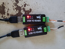
I use the below RS485 to USB Converters: Note the wire color to each converter.

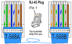
Using the T-568B (right), the orange/white and orange are pins 1&2 and the brown/white and brown are pins 7&8.

I take a cat5 ethernet cable, cut off one end, peel back the outer insulations and use the orange/white and orange twisted pair (pins 1 &2) connected as above to allow my computer to connect with and monitor all six LifePower4 batteries with the BMS_Test.exe software.
You can disconnect the RS485 to USB converter from your PC and plug it into the Raspberry PI USB port to monitor all batteries. Select "Narada" as the protocol.
Don't know what inverter you have but I use an EG4 communications Hub between my 6 Lifepower4 batteries and my SunGoldPower 10kw inverter. The hub converts the EG4/Narada protocol of the batteries to the Pylontec protocol for the Inverter. This also frees up the pins 1&2 RS485 bus on the batteries for Solar Assistant as the hub acts as the "Master BMS" and connects to all batteries on pins 7&8. There is a separate port on the hub for the inverter so the inverter does not use the pins 1&2 RS485 bus on the batteries.
The LifePower4 batteries implement two separate RS485 busses. Pins1&2 are one bus and pins 7&8 are the second bus.
The RJ45 connectors on the battery parallel, pins 1&2 and 7&8, that is to say pin 1 on connectors are connected, as are pin 2 to pin2, pin 7 to pin 7 and pin 8 to pin 8.
The Pin 7&8 RS485 bus is used for battery to battery communications between each battery and the "Master BMS" (address 0). Pins 1&2 are used for BMS to Inverter Communication (closed loop) or for communications with the BMS_Test.exe software or Solar Assistant. Please note that pins 1&2 cannot be used for more than one communication, i.e. Inverter, PC or Solar Assistant.
I use the below RS485 to USB Converters: Note the wire color to each converter.

Using the T-568B (right), the orange/white and orange are pins 1&2 and the brown/white and brown are pins 7&8.

I take a cat5 ethernet cable, cut off one end, peel back the outer insulations and use the orange/white and orange twisted pair (pins 1 &2) connected as above to allow my computer to connect with and monitor all six LifePower4 batteries with the BMS_Test.exe software.
You can disconnect the RS485 to USB converter from your PC and plug it into the Raspberry PI USB port to monitor all batteries. Select "Narada" as the protocol.
Don't know what inverter you have but I use an EG4 communications Hub between my 6 Lifepower4 batteries and my SunGoldPower 10kw inverter. The hub converts the EG4/Narada protocol of the batteries to the Pylontec protocol for the Inverter. This also frees up the pins 1&2 RS485 bus on the batteries for Solar Assistant as the hub acts as the "Master BMS" and connects to all batteries on pins 7&8. There is a separate port on the hub for the inverter so the inverter does not use the pins 1&2 RS485 bus on the batteries.


