Thank you
@smoothJoey and
@mikefitz for your comments.
You two are both right about the fuse rating for the fuse in between the (+) bus bar and the inverter. In our initial draft of the diagram, we had a bigger fuse size (
Here is another thread regarding those choices). When we noticed that we had already purchased a 4S 12V
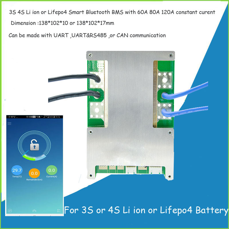
120A BMS, we decided to be protective of the BMS and have some fuses that have a smaller rating. After we made this second diagram and researched more about the specs of our BMS, we found
this post on the forum pointing that our BMS has 30 MOSFETs (
HY4903B6). Based on the datasheet each MOSFET can handle 1116 A of impulsed drain current (I think this is related to short circuit situations) at 25ºC. And depending on the temperature it can handle 222 A - 314 A of continuous drain current (just need to make sure there is a good heatsink available). So maybe a momentary surge current from the inverter would not damage the BMS. Also, another reason why we chose this BMS was that the max recommended charge/discharge rate for our cells is 0.5C (280A / 2 = 140A, max 140A per hour) Also, we are planning to not use the inverter heavily with our current setup. We also contacted Giandel, the inverter manufacturer, on Amazon and they suggested using a 200 A fuse (
link to the Q/A). Based on your suggestion should we change this part of the diagram to:
(+) bus bar ---
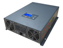
250A fuse --- (2/0 AWG) --- 200A Circuit Breaker --- (2/0 AWG) ------------ 2200 W, 12 V Inverter
In the video you shared,
@mikefitz , by
@Will Prowse , he suggests not pushing MOSFET type BMSs more than half of the current rating. So in our case with the 120A BMS, that would be 60A. That's another thing to keep in mind for us, to have our continuous discharge currents less than 60A.
In the first draft, we also had a bigger class T fuse protecting the main line / positive terminal of the battery pack. We had a 350A class T fuse and we went ahead and purchased one. So we have a class T 350A fuse in hand if we decide to use it. Should we incorporate the 350A fuse there, or would you say to go and get a 300A one for this leg of the diagram?
(+) Battery Terminal --- (2/0 AWG) --- 300A or 350A class T fuse ? --- (2/0 AWG) --- (+) bus bar
Also, is the 150A fuse between the DC fuse box and the (+) bus bar ok?
(+) bus bar ---
150A fuse --- (2/0 AWG) --- DC Fuse Block
There may be a problem with the inrush current into the inverter at first connection shutting down the BMS. If this an issue use a filimant bulb in series with the positive supply to pre charger the input capacitors in the inverter. I am using the same BMS that you are considering and have had no problem.
We just learned about this inrush current with inverters and noticed folks suggesting to put a bulb or a resistor when first connecting the inverter. We need to learn more about this. Thank you for mentioning it.
Auto transfer switch, this area needs consideration, you dont want the inverter feeding the battery charger.
Depending on local regulations or personal requirement you may need to add protective systems for over current and electric shock for the AC circuits.
That is true. We knew about this problem and thought that the auto transfer switch that we selected only supplies current to the charger from the shore and not from the inverter lines. We have the
Go Power TS-30 ATS. This unit might be a rebranded Progressive Dynamics ATS. We found this diagram for our ATS:

How would we check to see if this ATS does not allow a loop from battery > invertor > ATS > charger > battery?
Also, what kind of protective systems do we need to have to meet the local regulations for over-current and electric shock from the AC circuits?
We have already purchased the MPPT charge controller. We went with EPEVER MPPT Solar Charge Control (
Tracer4215BN) since it can be highly customized (in its settings) based on other people's recommendations.
And also have already purchased the 4S 12V 120A BMS from
aliexpress. It came with three 10 AWG wires soldered on each side.
16 feet round trip is getting long for the inverter wire.
You only need 6 awg for the fuse box and you probably don't need the fuse box as you already have the combined ac/dc distribution panel.
Suggest you get and inverter/charger to replace the inverter, ac charger and transfer switch.
You don't need 2/0 for the ac charger 6 awg will do fine.
You should have a dc2dc charger between the alternator and the house system.
We roughly put in the measurements for the wire lengths and over-speced the wire gauges to be on the safe side. It is kind of hard to know how far the devices/components are from each other before putting them all together. The inverter probably going to end up way closer to the positive bus bar and the battery pack.
Based on the wire length, max capacity of the DC Fuse block (100A) and 1%-3% voltage drop, we calculated that we needed to use 1/0-4/0 cable between the (+) bus bar and the DC fuse block. Again, it's probably over-speced. The RV AC/DC panel is only connected to a few AC power outlets and water pump, interior lights (and 2 more things). But there is no more room to add more fuses for more DC appliances such as USB chargers, ... .
The inverter/chargers that we came across with, for example, the ones from Victron, seemed out of our budget. That's why we didn't go with them. Do you have suggestions for cheaper ones that still are of good quality?
Yes, we have over-speced for the ac charger cable as well. Based on the calculations we did and the range of wire gauges that we ended up with for each section of the diagram, it made more sense to pick mostly 6 AWG and 2/0 AWG cables and order in bulk.
You are absolutely right for placing a DC2DC charger between the alternator and the house system. We are still contemplating if we should hook up the solar battery pack to the alternator. We are worried we might end up burning the alternator. Would you recommend using the alternator as another power source for the battery pack? If we do decide to go this route, we would probably get the
Orion-Tr Smart DC-DC Charger 12 | 12 - 30.
Also, we have another conversation going about our diagram on reddit. If you are interested, here is the link: