diy solar

diy solar

New no battery pure sine wave solar power system with smart switchers.

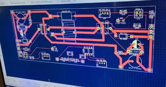
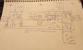
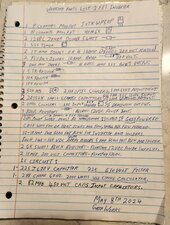
Good morning, up at 5AM in preparation for another dual 140VDC solar test on the two FET inverter.

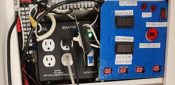
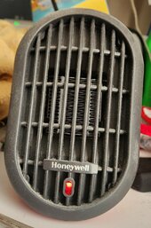
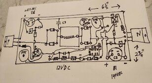
What is different this time around is the project system has been powered down so I can fully access and test the 10amp ISO transformer output from the new two FET inverter. Hopefully the inverter will push the level one quartz tube heater and lamp directly off the built-in outlets on the front of the ISO transformer.

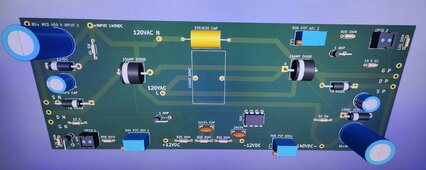
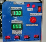
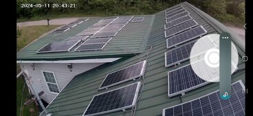
Each solar input is fused at 5amps seven series panels 140VDC and the ISO transformer is fused at 10Amps, Previous low voltage testing says this might just work.

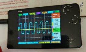
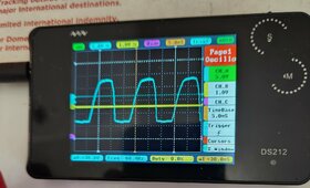
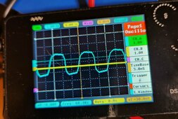
Wish me luck, expect full sun this morning for a short time, running the best sinewave output from the inverter to the ISO transformer hoping for a home run running loads and pure sine output off the transformer.

If this test is successful next stop is dual 160VDC eight series panels each input testing.

Will post more today as testing continues, If successful more information and photos will be posted.

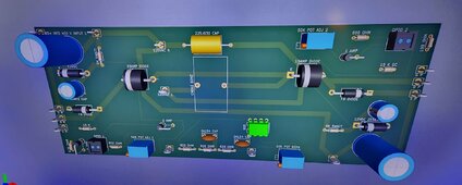
Have a set of fixed resistors 20.5K and 39.1K for the inverter but not going to use till later using 50K potentiometer so I can make small adjustments to the output.

More very soon 😀
 
Last edited:
Mixed results from testing:

ISO transformer runs much quieter but only transferring approximately 50% of the input power, your best bet right now is to run loads directly from the two FET inverter.

Once full sun is on the panels the inverter runs stable but if you add the ISO transformer the power output wavers a bit in 3 second intervals.

During low loads on the inverters output voltage is a bit high leading me to believe dual 140VDC is the correct input voltage for the new two FET inverter.

Everything seemed to work OK but best results were when the inverter was directly pushing the loads.

The Project Systems pure sine output is superior in pushing the ISO transformers. (Recommended).

I don't really understand everything that was going on during this test but the inverter has not been damaged by all the things I have tried, Have repeatedly stopped and started the inverter with and without the ISO transformer with no damage done.

Don't know if it will help ran into a YT video that had a small LC circuit directly connected to the 555timer turning the square wave into sine, wonders what happens if I use this as a FET trigger 🤔


More later 😀
 

Attachments

  • 20240505_074808~2.jpg
    20240505_074808~2.jpg
    224.2 KB · Views: 9
  • 20240505_084916~2.jpg
    20240505_084916~2.jpg
    368.4 KB · Views: 4
  • 20240505_074337~2.jpg
    20240505_074337~2.jpg
    119 KB · Views: 12
  • 20240505_085152~2.jpg
    20240505_085152~2.jpg
    183.9 KB · Views: 11
  • 20240505_074447~2.jpg
    20240505_074447~2.jpg
    256.7 KB · Views: 4
Last edited:
Made a decision to return the Project system to the 5+5+5=15 amp 180VDC configuration for the summer ☀️

I will make new diagrams and parts list for what is working now, I invite you and others to build,use and improve upon the two FET inverter designs.

Work will start on a two side Printed Circuit Board (PCB) for the 2 FET inverter, only mystery is the pure sine choke value in MH for the LC circuit, any help in testing this part for value ?

New inverter will be the same size as the project power board in the long direction for easy case mounting or heat sinks.

Project system restored to normal, Picture, Only need one more change in the rooftop solar panel wiring to be finished for the day.

Taking a break for now, best wishes
 

Attachments

  • 20240505_120605~2.jpg
    20240505_120605~2.jpg
    222.2 KB · Views: 1
Last edited:
Inverter runs smooth in this low drive mode have not lost a Mosfet/FET since heading down this path. Avoid any spikes on the oscilloscope inverter output.

Literally go from zero output to FET starting then adjustment for a sweet spot just a notch higher. Power is not as clean as the project power system but have found it to be useful for lighting,small heat, small electronics and wound motors. Low heat generation from the FETs.

Keep the voltage above 100VAC and the new two FET inverter just keeps going.💚

Additional information in some of the previous posts. This inverter will translate into a small circuit board that will fit in your hand, Groups 7 standard 12VDC solar panels, Minimum B1 7 panels B2 reverse 7 panels, Need more amperage parallel 140VDC sets B1 (7) and (7), B2 (7) and (7) and so on.


More soon 😀
 
Last edited:
Note worthy things about the new two FET inverter.

Low heat generation from the FETs suggests energy efficient operation.

Interesting response to a surge condition at first (first second) it looks like the inverter may fault but it just keeps pushing more and more watts into the situation. Was worried about needing a soft start but the unit builds behind a start up load nicely, most watts I have seen to date is 650 for the two FET inverter.

Stable 59.5 to 60.4 Hz operation good sine wave and easy adjustment to 50Hz if needed.

Operation at the best sinewave low end operation of the two FET inverter has resulted in no MOSFETs failures in the past three live solar panel testing at dual 140VDC and 180VDC.😀

Simple design and with terminal strip for the FETs mount and connections you can change out parts in minutes if ever needed.

If your into electronics give it a try have had loads of fun building this inverter, Like lighting up twin jet engines one forward and one reverse since both are synced 120VAC 60Hz power is extracted efficiecently from the process.❤️

Best wishes
 
Last edited:
Just an early attempt at a printed circuit board lay out all wires that jump another wire go to the bottom layer of the circuit board traces.

Next attempt will be to get the 555timer, optic couplers and floating power supplies area accurate and spaced.

Accurate drawings and parts list soon, this is just a doodle but considering actual physical parts lay out and size.
Need to add the additional support components around the FETs.

First draft. 50K potentiometers belong on the optic couplers input not the gate triggers, fix it next go around.

On a second thought testing two 25K potentiometers in that location has never been tested yet 🤔

More soon 😀
 

Attachments

  • 20240506_222436~2.jpg
    20240506_222436~2.jpg
    213.2 KB · Views: 8
Last edited:
Currently working on parts list and diagrams/printed circuit board for the two FET inverter. Just a couple more days to complete the drawings.

The LC for a 555 timer to turn the square wave into sine is 288 uH choke with a 10 uF (works) to 24 uF capacitor (calculated). Have photo examples of the 1000watt and larger 2,000 watt chokes in several previous post.

Going to use my 60Hz 555 timer dual output optic driver circuit to drive a four N channel FET single DC input inverter of my own take of the project power board, If I can get the 555timer to work via a 12VDC floating power source it may not even need the optic couplers.

Planning to use an online PCB card maker initial order of 20 - 30 circuit boards. 6 1/2" wide by 2 3/4" tall.

Another pre draft of the printed circuit board layout

More later 😀
 

Attachments

  • 20240507_214550~2.jpg
    20240507_214550~2.jpg
    268.6 KB · Views: 2
Last edited:
How about the correct parts list for the new two FET inverter.❤️

Brain cells were abused in the production of this list, alot of forward thinking and cost reduction thoughts went into this choice of parts.

Money goes into the output FETs for serious power production P FET is tough as nails and the 40N65 FET has a proven track record.

Ask questions if you need assistance, one more day on the main circuit drawing.😀

Best wishes

Added DC input capacitors to the list.
 

Attachments

  • 20240508_230304~2.jpg
    20240508_230304~2.jpg
    205 KB · Views: 6
Last edited:
Main drawing now passes first audit, Need to redraw at least one more time before it is published caught missing input capacitors on the parts list during audit.

Killed two or three birds with one stone by just organizing part location and direction. After rotating things a bit the whole inverter became more simple this will help in making a circuit board also.

More soon 😀
 
Here it is moved potentiometers around and simplify a few things, Official circuit design of the new two FET inverter.❤️

800 ohm resistors are optional protection for the optic couplers from too high of a setting, set all potentiometers for increasing value in the clockwise direction, (Start all potentiometers at a minimum setting) ( First test dual 9 VDC on inputs nothing can be damaged and you can see/adjust everything.) Passing the dual 21VDC bench test or higher means the unit will likley tolerate 140VDC dual solar input, This a early release of Version 1.0 of the new two FET inverter, expect refinement and a nice circuit board soon to mount the components in kit form, Two FET inverter will be compact and versatile.

Use a 25 watt standard light bulb or equivalent as minimum load on the inverter 24/7. Stability issue.

Expect more improvements highest output so far 650 watts 120 VAC 60Hz 550 watts was long-term tested.

Enjoy and ask questions if needed.⚠️after connecting the capacitors to higher voltage you must follow discharge procedures before servicing the unit!

I am going to improve the circuit diagram and audit it again, If I have a mistake the time to catch it is now.

Have plenty of alligator clip jumpers available will do a physical recreation of the optocoupler to FET output per the Official design on the second test inverter to complete the audit and report back to everyone 😀 Have plenty of new parts to test.

More soon 😀
 

Attachments

  • 20240508_230304~2.jpg
    20240508_230304~2.jpg
    205 KB · Views: 7
  • 20240514_182442~2.jpg
    20240514_182442~2.jpg
    319 KB · Views: 1
Last edited:
Off to a good start with Micad for printed circuit board production (PCB) and gerber file handling, purchased grid paper for better quality diagrams, starting a real world audit of the two FET circuit diagrams, I will update you as it progresses, if I have a bug it needs to be fixed now.

Audit of P channel has began, N channel is exactly like the previous circuit diagram the one with the two bulbs, I am going to be meticulously testing everything 😀

Old dog is going to learn a new trick, Online videos can teach you new skills, Interest in electronics hobby has declined overall in recent years.

More soon 😀
 
Last edited:
Found mistakes in the diagram on the two, 12VDC floating power supplies, The 10 Mfd 200volt capacitors belongs accross each 12VDC zener diode, once the second inverter preforms on the bench test properly I will issue a new drawings.

Sorry but it will be corrected soon, Glad to have the one and only working example to compare everthing to.

Best wishes, Sorry more soon.

Picture diagram:

Quick fix to show the correct capacitor placement in the plus and minus 12VDC power supplies, New best diagrams ever after successfully testing.

Give me a day or two to properly fix and audit everything.
 

Attachments

  • 20240514_182442~2.jpg
    20240514_182442~2.jpg
    319 KB · Views: 1
Last edited:
Still need to complete a full physical audit on live parts, this Diagram is based on the actual working two FET inverter and contains fixes and improvements.

The two 12VDC floating power supplies were wrong on the previous Diagram, improvement made in the 555 output to the diodes.

Just need a second working example to start the process, Notice the open spaces this thing could shrink down to almost nothing with modern parts, going with classic parts and 6 inches in the long direction for easy FET mounting options.

Bench testing every day, unit running smooth 😀

Diagram is the best so far, basically the result of two ongoing audits, Can not proceed properly till it runs a second time on new/tested parts, Making progress on all fronts.

Pressure washed all the solar panels today,Nice 😀

Last picture is the new diagram configuration running on the two FET inverter. Audit successfully completed all fixes and updates working.
❤️

Whew ! Newest configuration works great and first time.

Last diagram most updated version of the new two FET inverter. Sorry for mistakes here is the one you really want.

More soon 😀
 

Attachments

  • 20240508_230304~2.jpg
    20240508_230304~2.jpg
    205 KB · Views: 8
  • Screenshot_20240511_204321_CloudEdge.jpg
    Screenshot_20240511_204321_CloudEdge.jpg
    300.7 KB · Views: 1
  • 20240511_212542~2.jpg
    20240511_212542~2.jpg
    268 KB · Views: 1
  • 20240514_182442~2.jpg
    20240514_182442~2.jpg
    319 KB · Views: 2
Last edited:
See previous post, Circuit passed audit and live testing.❤️

Three days in a row the Project system has run the Mini-split plus house lights,fans circuit,mini fridge, two computer monitors and two stick computers 8:30 AM to 5:30 PM no glitches or errors except lights dim a moment when mini fridge starts.💚

No battery grid backed secondary operation works 99% of the time.❤️

Many use options available ✨

More later
 
Last edited:
Slow start on PCB cad program, but going to double down on the effort starting tomorrow.

Although I have been able to label (silk screen) text and place some parts on a circuit board much more study is needed to build the two FET inverter board I have in mind.

More later 😀
 
See any improvements?

Back/bottom layer traces are there but not very visible.

Getting very close now, program shows no errors😍

More soon

Enough spare new parts to build one tomorrow if I had the PCB, a couple more days and the gerber files will be ready for export, hope to get bright red green and blue/purple new power boards ❤️

Small,light weight, low cost power boards.

Just caught a mistake N FET 40N65 is missing two support components and the 100 ohm resistor does not belong on this side, must get everything right before going to make duplicate circuit boards.

Updated photos, last is latest

DRC test passes with 5 silk screen warnings, making Gerber export files❤️

More soon 😀
 

Attachments

  • 20240515_130307~2.jpg
    20240515_130307~2.jpg
    332 KB · Views: 1
  • 20240515_130343~2.jpg
    20240515_130343~2.jpg
    276 KB · Views: 1
  • 20240515_152950~2.jpg
    20240515_152950~2.jpg
    178.4 KB · Views: 4
  • 20240515_194731~2.jpg
    20240515_194731~2.jpg
    177.5 KB · Views: 2
Last edited:
Making progress, Will likely order circuit boards tomorrow 😀

Zero errors on the files fixed everything.one more audit on the circuit board.

New pictures,test pins removed,passed audit, Whew hot off the press New two FET inverter.


Fixed all through holes, ready to order now😍

More soon
 

Attachments

  • 20240515_194731~2.jpg
    20240515_194731~2.jpg
    177.5 KB · Views: 2
  • 20240515_194814~2.jpg
    20240515_194814~2.jpg
    255.1 KB · Views: 1
Last edited:
10 green circuit boards ordered, $35 for the product and $23 shipping, So about $6 each for the two FET inverter board 😀
Uploaded about 12 .gbr files in a zip file but order did not pass because the drill file was missing, I should make a YT video now that I figured out how it is done.

Zip file available to anyone who wants it contains. Grb files and drill files nessassary to make/reproduce this Version 1.0 circuit two FET inverter board, may post on git hub in a few days.


Excited to say the least, More soon
 
Last edited:
Thanks for ALL your work,
-will more 85 mfd 450v improve work ,ie motor start
-do you plan to use ISO on outside
Best
 
Back
Top