diy solar

diy solar

Troubleshoot extremely low amps with my solar setup

Armonius

New Member
Joined
May 12, 2024
Messages
10
Location
Tampa, Florida
Hello people of diysolar. I have been lurking on here for some weeks now. And a circumstance has occurred that gave me a reason to create an account!
I set up solar on my school bus from last year December. And it's been working fine up until May. It's slowly started taking longer and longer to charge my batteries.
At first I thought it was a bad crimp on the terminal connection that connects the positive side to my charge controller.
Before I dive into my troubleshooting tactics, let me list my setup
4 425watt solar panels wired in parallel
2 12v 200ah Litime/Ampere Time lifepo4 batteries wired in parallel
1 2500watt inverter
1 bateria Sunrock 80A MPPT charge controller or Growatt SC48120 MPPT charge controller
When I look at my MPPT, the watts coming from PV is 11. Max I have seen it go to is 50. Something is awfully wrong here. I know it's the amperage because I'm getting good voltage. (170-190 depending on the day) And the PV voltage often stays at 0-2 on the charge controller. I've measured the voltage and amperage for each solar panel and I've gotten good voltage (all read 170-190) and amps are reading 1 for each of them. I thought it was the y branch connectors that were bad, so I replaced them today and nothing changed. What else can I try? The batteries are at 12.8-12.9 for the past two days with barely any power going into them
 

Attachments

  • IMG-20240507-WA0001.jpg
    IMG-20240507-WA0001.jpg
    120.6 KB · Views: 12
~2 kW with 4 panels on parallel is a lot of amps for that wire on a y plug from the SCC to the battery. I suspect something is bad on that wire run, especially with unusual readings into the SCC that you did not get before.

- test voltage of each panel on the roof at the connector going into the y connector. They should be close.
- leave only 1 connector plugged, and test voltage coming out of the y cable. Should be the same.
-test volts going into the SCC, this should be close to the volts at the roof. Usually you can check voltage at the PV in lugs on the SCC.

I would suspect bad connections whether it’s a loose lug on the PV in of the SCC, corroded wire, bad connection if the wire is crimped elsewhere. Might even be a spare inline fuse. Also, a on off switch sticking.

The charge controller could be bad, so you could swap around SCCs if able.

If everything works with the one panel, add panels back in until failure.
 
I had cheap MC4 connectors. The male pins did not stay in place, they would be pushed back into the plastic. The metal tangs would get bent. I was only getting partial power when it was bad. I fixed it with epoxy. I was camping remote and too far from deliveries.
 
I've measured the voltage and amperage for each solar panel and I've gotten good voltage (all read 170-190)
Something doesn’t add up here. You said there are four panels wired in parallel, so how are you measuring 170-190V anywhere? Maybe these are very different panels than I’m familiar with, but I don’t think I’ve ever seen a single panel Voc much higher than 60V.
Are you 100% sure that your multimeter isn’t showing 170-190 mV (milliVolts)?

amps are reading 1 for each of them.
It might be helpful to tell us how and where you’re measuring this. If it’s all connected in the system it probably isn’t telling you anything you didn’t already know. But if you’re trying to measure Isc, you need to short the panel by disconnecting it from everything else in your system and then connecting its positive and negative together.
 
~2 kW with 4 panels on parallel is a lot of amps for that wire on a y plug from the SCC to the battery. I suspect something is bad on that wire run, especially with unusual readings into the SCC that you did not get before.

- test voltage of each panel on the roof at the connector going into the y connector. They should be close.
- leave only 1 connector plugged, and test voltage coming out of the y cable. Should be the same.
-test volts going into the SCC, this should be close to the volts at the roof. Usually you can check voltage at the PV in lugs on the SCC.

I would suspect bad connections whether it’s a loose lug on the PV in of the SCC, corroded wire, bad connection if the wire is crimped elsewhere. Might even be a spare inline fuse. Also, a on off switch sticking.

The charge controller could be bad, so you could swap around SCCs if able.

If everything works with the one panel, add panels back in until failure.
I thought something was bad on the wire run, because I got 1 amps on each solar panel and then got 0.4 amps on the y branch connectors. But when I replaced them, with new mc4 y branch connectors, i still got the same result.

I did test the voltage of each solar panel and got 190-198 when in full sunlight on each panel. The voltage on the terminals that are connected to the charge controller was fluctuating between . I didn't leave only one solar panel plugged and then check each one through the y branch connector like you said. I'm definitely going to try that today..
I thought it was a bad connection at first. I looked at the mc4 connectors and they look okay, no overheating, they don't look deformed. Im wondering if it's my untrained eyes that don't know how to find the flaw. But I'm not sure myself what could be going wrong. I still see the male and female pins that look like they're in the right place
You mentioned a bad crimp? They would give off heat right? I would see something melted? How would I detect a bad crimp?. I bought a separate charge controller because of this issue and got the same result.
 
Something doesn’t add up here. You said there are four panels wired in parallel, so how are you measuring 170-190V anywhere? Maybe these are very different panels than I’m familiar with, but I don’t think I’ve ever seen a single panel Voc much higher than 60V.
Are you 100% sure that your multimeter isn’t showing 170-190 mV (milliVolts)?


It might be helpful to tell us how and where you’re measuring this. If it’s all connected in the system it probably isn’t telling you anything you didn’t already know. But if you’re trying to measure Isc, you need to short the panel by disconnecting it from everything else in your system and then connecting its positive and negative together.
I uploaded a photo of the back of solar panel here. I think these panels have very high voltage. Voc is 200+ and Vmp is 183. The amps are fairly low here. And yes Im positive that the setting is not on milivolts. The multimeter is on 600v and the PV voltage is fluctuating from 170-190, in full sunlight.
Sure. I'll try to walk you through what I did
I measured the voltage and amperage of each solar panel after disconnecting them at the positive and negative mc4 connector(voltages ranging 170-190, amps ranging 1-1.5 but I did measure the amperage when the sun was setting, but I'm in Florida so there was still 1hour plus )
I measured the voltage and amperage at the positive and negative terminals that are connected at SCC and got slightly less voltage but amps kept getting OL.
Can you explain to me how to measure amps properly? I have a multimeter and it's not quite working with me. It always says OL (assuming that's overload) when I try to measure amperage. And the 10A fuse isn't working at all. Every measurement just says 0. I bought the multimeter at harbor freight so I'm not expecting much. But I even got a DC/AC clampeter from harbor freight that just wasn't giving me good readings either. Is there some technique or trick I need to be aware of when measuring amps? And what's ammeter should I prioritize getting?
 
I uploaded a photo of the back of solar panel here. I think these panels have very high voltage. Voc is 200+ and Vmp is 183. The amps are fairly low here. And yes Im positive that the setting is not on milivolts. The multimeter is on 600v and the PV voltage is fluctuating from 170-190, in full sunlight.
Well I stand corrected on the panel voltage! Voc over 200V is a new one to me.
amps ranging 1-1.5 but I did measure the amperage when the sun was setting,
This actually seems about right. This is 1/2 to 2/3 of Imp, and with a setting sun is probably not far from what you should expect.

Can you explain to me how to measure amps properly?
This seems to a be a common problem... The easiest way is to get a clamp style multimeter that measures DC current (note: many only measure AC current, so make sure you're getting one that can read DC). Clamp it over any single wire in the circuit you want to measure, and it reads the current.
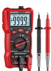
If you don't have one of those, and instead only have a mulitmeter that looks like this (not an endorsement, it's just what a lot of them look like):
1715614706182.png

Then you're limited to measuring no more than 10A (or whatever is printed on the case), and what you need to do is have the circuit you want to measure run through the multimeter. So if you want to measure current in 'normal' operation, you need to disconnect a wire somewhere and then connect the two ends you've created to the COM and 10A (in the example photo) terminals of the meter.
Note that internal to the meter, the path between the COM and 10A connections is essentially a short, with just a small resistance that is used to measure voltage and then infer current from the voltage drop. Just something to keep in mind so that you're aware that if you touch those probes across the input of your SCC, you'll be shorting your entire array. And if you try it across the output of your SCC, you'll be shorting your battery, and that would be very bad. See discussion here: https://diysolarforum.com/threads/circuit-breaker-spark.83808/
 
I had cheap MC4 connectors. The male pins did not stay in place, they would be pushed back into the plastic. The metal tangs would get bent. I was only getting partial power when it was bad. I fixed it with epoxy. I was camping remote and too far from deliveries
 
How did you tell this? Also how did you use epoxy to do this? And how long did they work for you? I want to know if it's a problem with my mc4 connectors but I'm not sure
 
Well I stand corrected on the panel voltage! Voc over 200V is a new one to me.

This actually seems about right. This is 1/2 to 2/3 of Imp, and with a setting sun is probably not far from what you should expect.


This seems to a be a common problem... The easiest way is to get a clamp style multimeter that measures DC current (note: many only measure AC current, so make sure you're getting one that can read DC). Clamp it over any single wire in the circuit you want to measure, and it reads the current.
If you don't have one of those, and instead only have a mulitmeter that looks like this (not an endorsement, it's just what a lot of them look like):
View attachment 215113

Then you're limited to measuring no more than 10A (or whatever is printed on the case), and what you need to do is have the circuit you want to measure run through the multimeter. So if you want to measure current in 'normal' operation, you need to disconnect a wire somewhere and then connect the two ends you've created to the COM and 10A (in the example photo) terminals of the meter.
Note that internal to the meter, the path between the COM and 10A connections is essentially a short, with just a small resistance that is used to measure voltage and then infer current from the voltage drop. Just something to keep in mind so that you're aware that if you touch those probes across the input of your SCC, you'll be shorting your entire array. And if you try it across the output of your SCC, you'll be shorting your battery, and that would be very bad. See discussion here: https://diysolarforum.com/threads/circuit-breaker-spark.83808/
I have the common multimeter. Thank you for that good tip you gave me on how to measure amps... I really appreciate it. Ive been trying to get good readings with it but I think harbor freight sold me one with a blown fuse.everytime I use the 10A one it just doesn't work
 
Okay! Update!. I got the DC clamp meter and seeing a decent reading of the voltages. The Growatt SC48120 charge controller that I have had a screw with really damaged threads so I also replaced them. I'm seeing full sunlight right now. But it is still not giving me strong amps. I measure the amperage and get 1.2, 1.4,0.9 and 0.8 for each panel in full sunlight( started cloudy but got back sunny). But the y branch connectors voltage is still giving me 0.4-0.8A. I don't understand. The PV amps is still showing 0.2-0.6A on the charge controller with no Watts also. Even with voltage showing 70-120.

I'm thinking that the configuration of the charge controller could probably mistake the SOC to full because the battery icon is filled, but that didn't happen before. Now it charges to 13.1 and doesn't really go much further than that
 
Well I stand corrected on the panel voltage! Voc over 200V is a new one to me.

This actually seems about right. This is 1/2 to 2/3 of Imp, and with a setting sun is probably not far from what you should expect.


This seems to a be a common problem... The easiest way is to get a clamp style multimeter that measures DC current (note: many only measure AC current, so make sure you're getting one that can read DC). Clamp it over any single wire in the circuit you want to measure, and it reads the current.
If you don't have one of those, and instead only have a mulitmeter that looks like this (not an endorsement, it's just what a lot of them look like):
View attachment 215113

Then you're limited to measuring no more than 10A (or whatever is printed on the case), and what you need to do is have the circuit you want to measure run through the multimeter. So if you want to measure current in 'normal' operation, you need to disconnect a wire somewhere and then connect the two ends you've created to the COM and 10A (in the example photo) terminals of the meter.
Note that internal to the meter, the path between the COM and 10A connections is essentially a short, with just a small resistance that is used to measure voltage and then infer current from the voltage drop. Just something to keep in mind so that you're aware that if you touch those probes across the input of your SCC, you'll be shorting your entire array. And if you try it across the output of your SCC, you'll be shorting your battery, and that would be very bad. See discussion here: https://diysolarforum.com/threads/circuit-breaker-spark.83808/
I got the dc clamp meter because my multimeter fuse was blown and I also got some new Y branch connectors and I'm still having the same issue. I measured the amps along the line for each panel and the further I get from the solar panel the lower the amperage gets to.. I don't understand. What could be causing so much resistance. I got some 4v1 branch connectors, and when I measure the amperage at the junction point(where all the 4 negatives are connected, i get 1.2-1.4 and when i go up, to the 1 wire, i get 0.7. I dont understand what is causing these drops in amperage
 
I measured the amps along the line for each panel and the further I get from the solar panel the lower the amperage gets to.. I don't understand.
I'm not sure what you mean here. In any circuit the current must be the same everywhere. It'll change once you combine circuits with your Y connectors, but even then, current into the Y equals current out of the Y. Resistance in the circuit decreases current everywhere, it doesn't gradually decrease as you get farther from the power source.
Now that you have a clamp meter, have you checked the Isc of each panel individually? I wonder if you don't have one that's causing problems and consuming power instead of making it. That could drag the whole array down.
To measure Isc, disconnect the panel from the system, then connect that panel's positive and negative together (yes, this is a short, and yes, it's fine), then use your meter to measure the current.
 
I got some 4v1 branch connectors, and when I measure the amperage at the junction point(where all the 4 negatives are connected, i get 1.2-1.4 and when i go up, to the 1 wire, i get 0.7.
A diagram of this (or photos) might be helpful, I'm having trouble envisioning what you mean.
DC clamp meters are directional, so you should be able to test if all four panels are moving current in the right direction; current flow should be the same polarity for all four wires coming into the Y.
 
A diagram of this (or photos) might be helpful, I'm having trouble envisioning what you mean.
DC clamp meters are directional, so you should be able to test if all four panels are moving current in the right direction; current flow should be the same polarity for all four wires coming into the Y.
Im going to take some photos today. I really apologize for dropping the ball on you all. I've been going insane trying to make some money and troubleshoot these things. I think we're in different timezones
 
I'm not sure what you mean here. In any circuit the current must be the same everywhere. It'll change once you combine circuits with your Y connectors, but even then, current into the Y equals current out of the Y. Resistance in the circuit decreases current everywhere, it doesn't gradually decrease as you get farther from the power source.
Now that you have a clamp meter, have you checked the Isc of each panel individually? I wonder if you don't have one that's causing problems and consuming power instead of making it. That could drag the whole array down.
To measure Isc, disconnect the panel from the system, then connect that panel's positive and negative together (yes, this is a short, and yes, it's fine), then use your meter to measure the current.
Maybe it's my DC clamp meter that's bad then? The current always changes when I move it up or down the wire. It also always gives me different currents on both the positive and negative. I always read that when I place two wires into the clamp it should give me zero because it would cancel out but that never happens. I don't understand how this one works. I always get different readings moving it up and down the wire. I'm thinking I can short the solar panels and measure the short circuit current, but I'm concerned whether it will damage the cells because these are high voltage solar panels. I can't find any information on it either.
 
I'm thinking I can short the solar panels and measure the short circuit current, but I'm concerned whether it will damage the cells because these are high voltage solar panels.
Shorting a single panel won’t damage it. When it’s shorted, voltage drops to zero (more or less) and you get basically free-flowing current that makes or consumes almost no power. In really good, full sunlight you should almost get the Isc rating.
 
4 425watt solar panels wired in parallel
The only panels I have seen with high output volts are flexible panels. If this is the case, it maybe one or more of the panels is damaged. Its common for a damaged flexible panel to show voltage but fail to deliver current. Since things worked well for some time but you now have issues, failed or partially failed panels could be the cause.
With the panels in parallel any panel fault could cause current to be directed to the faulty panel from the operational panels.

Using your DC clamp meter. Ensure it's actually capable of measuring DC. Unless its got a low range for current measurement, you may not get accurate results for the low currents you are measuring,

To measure the SC current short together the positive and negative cables from the panels, take care due to the high volts.
Hold the meter in the region either the positive or negative cable, set to zero on the meter to remove the influence of stray magnetic fields, clamp around one of the cables.
Idealy you need to measure the SC current of each panel separately.

My guess is failed panels.
 
Back
Top