diy solar

diy solar

SRNE 12kW IP65 HES and 10kW ASP

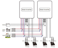
Proper way to connect 2 SRNE ASP inverters in parallel, I hope this helps resolve the question on how to connect them:

View attachment 212498
You are looking at page 23 of the manual. That is incorrect for 240V split phase here in the US.

This is what it states for the diagram you posted:

4.9.4 Wiring diagram for two-phase parallel connection (phase difference
between L1 and L2: 0°)
(1) P1: Set the item [31] to "2P0;" P2: Set the item [31] to "2P1," all of the P1/P2 inverter item
[68] can not be set, it is default “0°”and the phase difference between P1 and P2 is 120°.
When setting the item [38] to "120 V," the voltage between the live wire L1 of P1 phase and
the live wire L2 of P2 phase is 208 V, and the L1-N voltage is 120 V
(2) P1: Set the item [31] to "2P0;" P2: Set the item [31] to "2P2," all of the P1/P2 inverter item
[68] can not be set, it is default “0°”and the phase difference between P1 and P2 is 180°.
When setting the item [38] to "120 V," the voltage between the live wire L1 of P1 phase and
the live wire L2 of P2 phase is 240 V, and the L1-N voltage is 120 V, L2-N voltage is 120V


The correct page you need is page 28 which is for split phase 180° between L1 and L2 which is stated:

4.9.5 Wiring diagram for split-phase parallel connection (phase difference
between L1 and L2: 180°)
Set the item [31] to PAL, and set the item [68] to 180°. When setting the item [38] to
"120 V," the L1-L2 voltage is 240 V, and the L1-N voltage is 120 V, L2-N voltage is 120V

a. Two parallel-connected solar storage inverters:
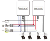

1714510812188.png

Note how L1 from each inverter is combined and each L2 is combined.
 
when does it arrive?
I'm waiting for clarity on if the parallel cables are included, they should be if the manual is correct. I'm also making sure I don't pay for wifi modules I don't need.
I should have checked the baba last night. They are on holiday from the 1st - 5th of May.
If all goes well they will be here by 5-20.
 
These inverters can be programmed to run 10kw single phase. I wonder if that is contributing to the diagram confusion. Are their separate diagrams depending on how each inverter is configured? Ie: programmed split phase vs each programmed single phase. I haven’t scrutinized them, just spitballing.
I believe you are correct, they can be programmed and wired both ways. Both diagrams are in the instructions.
 
I believe you are correct, they can be programmed and wired both ways. Both diagrams are in the instructions.
Man, can’t wait to be jumped on about breakers and output capacity again now 🤣
 
Man, can’t wait to be jumped on about breakers and output capacity again now 🤣
I'm still waiting on a response about what exactly the real output is when in parallel. My guess is the table is for a single inverter in split phase it would be 63A on each leg as peak output is 7500W. That works out to the 63A.

Peak surge in parallel would be 125A per leg.
 
I'm still waiting on a response about what exactly the real output is when in parallel. My guess is the table is for a single inverter in split phase it would be 63A on each leg as peak output is 7500W. That works out to the 63A.

Peak surge in parallel would be 125A per leg.
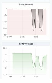
You got me thinking about how I can test, it should be easy enough. Here's the front and rear burner plus the stove oven on my ASF. 2 more burners and the dryer should easily get me to 20Kw.
Screenshot_20240430-211029.jpg

Does that voltage sag look normal for 3 packs in parallel? (two 230ah, one 304ah)

Screenshot_20240430-211418.jpg
 
Last edited:
I'm still waiting on a response about what exactly the real output is when in parallel. My guess is the table is for a single inverter in split phase it would be 63A on each leg as peak output is 7500W. That works out to the 63A.

Peak surge in parallel would be 125A per leg.
That is how I interpreted it also - but I am probably not the sharpest tool in the bag….
 
63 amps is just the breaker size they recommend. The output is 10000 watts, that is 5000 watts per hot leg, l1 5000, l2 5000, that equals 10000, or approx 42 amps at 240 volts. So they are taking 42 amps times 150% that equals 63 amps.
 
63 amps is just the breaker size they recommend. The output is 10000 watts, that is 5000 watts per hot leg, l1 5000, l2 5000, that equals 10000, or approx 42 amps at 240 volts. So they are taking 42 amps times 150% that equals 63 amps.
So using the watts / volts math 2 inverters would be 83.3A x 150% = 125A. So running each inverter into 60a breakers in a dedicated panel (call it the feeder panel) then running 1 awg wire from feeder panel to loads panel via its 100a breaker would be OK I assume.
 
So using the watts / volts math 2 inverters would be 83.3A x 150% = 125A. So running each inverter into 60a breakers in a dedicated panel (call it the feeder panel) then running 1 awg wire from feeder panel to loads panel via its 100a breaker would be OK I assume.
I would say that would work. Personally I would size the inverter breakers at 50 amps each, but that is just me.
 
Does that voltage sag look normal for 3 packs in parallel? (two 230ah, one 304ah)

170A, 1.1V is 0.00647 ohms.
Divide by 16s, 0.0004 ohms or 0.4 milli-ohms.

Measured where?
Individual cells I've seen spec of 0.25 milli-ohms and reported measurements of 0.17 milli-ohm.
But you've got 3 in parallel, so looking for 0.08 or 0.06 milli-ohms per cell. Instead I get 0.40 milli-ohms per cell.

But if there is 5 milli-ohms of battery cable and BMS in the path to where voltage is measured, then it is explained.
 
The drawing is direct from the SRNS Power Store on Aliexpress. When you run a single SRNE 10Kw ASP inverter in single phase mode you will get 120 Vac out at 10,000 watt (126 max amps gives you the 15Kw listed in the specs). In split phase mode, for a singe inverter you will only get 120Vac 5000 watts on L1 to neutral and another 120 Vac 5000 watts on L2 to neutral. Combined L1 to L2 dives you 240 Vac at 10Kw (63 max amps gives you the 15Kw listed in the specs) , At least according to what I've read about them so far. Just remember to have the AC breakers off on the inverters and then change the settings in the inverters to tell what you are connecting them to....
 
You are looking at page 23 of the manual. That is incorrect for 240V split phase here in the US.

This is what it states for the diagram you posted:

4.9.4 Wiring diagram for two-phase parallel connection (phase difference
between L1 and L2: 0°)
(1) P1: Set the item [31] to "2P0;" P2: Set the item [31] to "2P1," all of the P1/P2 inverter item
[68] can not be set, it is default “0°”and the phase difference between P1 and P2 is 120°.
When setting the item [38] to "120 V," the voltage between the live wire L1 of P1 phase and
the live wire L2 of P2 phase is 208 V, and the L1-N voltage is 120 V
(2) P1: Set the item [31] to "2P0;" P2: Set the item [31] to "2P2," all of the P1/P2 inverter item
[68] can not be set, it is default “0°”and the phase difference between P1 and P2 is 180°.
When setting the item [38] to "120 V," the voltage between the live wire L1 of P1 phase and
the live wire L2 of P2 phase is 240 V, and the L1-N voltage is 120 V, L2-N voltage is 120V


The correct page you need is page 28 which is for split phase 180° between L1 and L2 which is stated:

4.9.5 Wiring diagram for split-phase parallel connection (phase difference
between L1 and L2: 180°)
Set the item [31] to PAL, and set the item [68] to 180°. When setting the item [38] to
"120 V," the L1-L2 voltage is 240 V, and the L1-N voltage is 120 V, L2-N voltage is 120V

a. Two parallel-connected solar storage inverters:


View attachment 212508

Note how L1 from each inverter is combined and each L2 is combined.
You are correct, my bad, I didn't notice the 0 degrees between phases part.... Page 28 of the manual is the correct way for North America.
Thanks for the correction, greatly appreciated.
 
If you want to use that much wire. Personally, I'd install a trough and use either the junction blocks inside or Polaris type connectors. If you want to cheap out, then use a junction box close to the inverters with junction blocks or Polaris type connectors but usually by the time you buy a nice rated box, you might as well buy a trough. I need to start looking for one.

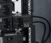
Inside the breaker box you will need either a two lug terminal or a Polaris type connector.

I agree this would make the wiring the simplest, but being able to shut off one breaker and isolate one of the inverters quickly could have its benefits.
 
170A, 1.1V is 0.00647 ohms.
Divide by 16s, 0.0004 ohms or 0.4 milli-ohms.

Measured where?
Individual cells I've seen spec of 0.25 milli-ohms and reported measurements of 0.17 milli-ohm.
But you've got 3 in parallel, so looking for 0.08 or 0.06 milli-ohms per cell. Instead I get 0.40 milli-ohms per cell.

But if there is 5 milli-ohms of battery cable and BMS in the path to where voltage is measured, then it is explained.
That would have been the measurement from the inverter. There is about 5' of 2/0 cable in between along with BMS, Class T fuse, bus bar, lugs and Midnite breakers.

Thank you for the check and math.
 
I agree this would make the wiring the simplest, but being able to shut off one breaker and isolate one of the inverters quickly could have its benefits.
How are you isolating one of the inverters with a double pole breaker turned off?

That shuts off both inverter outputs when wired like this.

1714578225064.png

I don't know if I would wire this in using single breakers, double pole would be ideal.
 
I'm still waiting on a response about what exactly the real output is when in parallel. My guess is the table is for a single inverter in split phase it would be 63A on each leg as peak output is 7500W. That works out to the 63A.

Peak surge in parallel would be 125A per leg.
how long is the peak surge? probably no breakers would pop that fast?
How are you isolating one of the inverters with a double pole breaker turned off?

That shuts off both inverter outputs when wired like this.

View attachment 212620

I don't know if I would wire this in using single breakers, double pole would be ideal.
having a double pole breaker per inverter? regular way to do it from what I've seen in other setups.
which is why it's also better to have each of them doing split phase so you can just turn 1 off if you need to do something and the system still has 5000 watts on each leg

like from will's old videos:
each split phase has this setup:
1714587016893.png
so as you grow the system you just add more & more 2 pole breakers on the right side
 
I'm waiting for clarity on if the parallel cables are included, they should be if the manual is correct. I'm also making sure I don't pay for wifi modules I don't need.
I should have checked the baba last night. They are on holiday from the 1st - 5th of May.
If all goes well they will be here by 5-20.
Should be because of the different ways it can actually be wired with those connectors.. I wouldn't trust any other type of wire with those connectors to be the exact same pinout as what they're doing unless it's "straight through" pairing then maybe many wires are the same (still not all)
It's weird they didn't just use rj45 and cat5 or cat6..
 
Back
Top