rin67630
Solar Enthusiast
And the smart shunt for all of them?2 Epever 4215bn, each with an MT50 display, and a Victron 150/45 SmartSolar MPPT. So 3 solar controllers, all attached in parallel to a 24V ~480AH battery pack.


And the smart shunt for all of them?2 Epever 4215bn, each with an MT50 display, and a Victron 150/45 SmartSolar MPPT. So 3 solar controllers, all attached in parallel to a 24V ~480AH battery pack.
Yes. Between the battery and rest of the world so I can count AH in and out of the batteries. The inverters - 1 Samlex 600W PSW that is electrically quiet for my 125W 24/7 loads, and my PC's that consume another 250W), and 1 Victron 24/1200, for charging my EV, and in an emergency run the fridge and freezer as it can actually start them.And the smart shunt for all of them?
Totally interested and up for it. FWIW, I prototype, build, and do PCB layouts mostly as a hobby, sometimes for work, usually using smt parts. Not much scares me. Enjoy your trip - looking forward to details when you get the time!If you don't mind to tinker a little bit wiring a dozen of wires on a prototyping board,
I can provide a variant that does the same as a Victron smart shunt e.g. for your two Epever SCCs and / or the inverters.
I have already done it as an ESP8266 data logger.
The bill of materiel will roughly be:
-An ESP8266 (e.g. Wemos -D1)
-An INA226 voltage / current monitor board e.g. https://www.ebay.com/itm/386196324315
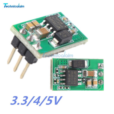
-A micro buck converter to DC 5V
-A soldering prototyping board
-A power shunt (if not already present)
-Optionally an OLED display for the Wemos-D1 if you want a local display.
It will be able to monitor batteries up to a voltage of 36v (24V nominal) and currents determined only by the shunt used.
And the best: it will send it's data over WiFi to a Victron-On-Steroids device ! (beside doing it to Telnet and -if required- to Thinger.io)
I am on a family trip and can't post a picture yet, but will upload asap the code to Github. The rest following in January.
I have drawn the schematic:Totally interested and up for it. FWIW, I prototype, build, and do PCB layouts mostly as a hobby, sometimes for work, usually using smt parts. Not much scares me. Enjoy your trip - looking forward to details when you get the time!
 github.com
So if you have the stuff at hand, so please check the intermediary projectTotally interested and up for it. FWIW, I prototype, build, and do PCB layouts mostly as a hobby, sometimes for work, usually using smt parts. Not much scares me. Enjoy your trip - looking forward to details when you get the time!
github.com
have you been going 88 miles an hour in your DeLorean again?Finally I will use a cheap ESP8266 as the hardware-base for all measuring units with each the capability of reporting one device/battery (Telnet/Thinger.io/UDP)
Later I will use an ESP32 that has more memory to aggregate several ESP8266 over WiFi/UDP to make one wireless central reporting and local display unit.
2014 will be a good year...
") ?️
?️ 
typo corrected...have you been going 88 miles an hour in your DeLorean again?
not sure what you mean by mini-buck, but these work well and support up to 60V for a nominal 48V system..Have you a better solution? A mini buck converter that accepts 35V?
A link was given in my post.not sure what you mean by mini-buck...
//----------------------- HARDWARE OPTIONS ---------------------------------

#define AO_IS_NONE        // _NONE , _DOUBLE-BATTERY , _HALF-BATTERY , _PANEL
#define D7_IS_NONE        // _NONE , _VICTRON
#define OLED_IS_NONE      // _NONE , _48*48 , _128*48
#define INA_IS_NONE       // _NONE , _226
#include "MPPT_75_15.h"
#include "LIFEPO_24_100.h"

//----------------------- SOFTWARE OPTIONS ---------------------------------
#define WEATHER_IS_NONE   // _NONE , _OWM             // (Source of the Weather Information)
#define DASHBRD_IS_NONE   // _NONE , _THINGER         // (Internet Dashboard)
#define UDP_IS_NONE       // _NONE , _SEND , _RECEIVE // (UDP Inter-ESP Communication)
#define UDP_ADDR   "192.168.188.32"                   // (IP of the receiving ESP)
#define UDP_PORT   4200                               // (Port used to send/receive Values to other ESP)
....Who are the questions aimed at?So you can define
I am not directly asking questions, but I would be happy to hear from you, if I am doing it in a way that is useful and understandable for the most people.This is all progressing quickly
Who are the questions aimed at?
, I'd read that as "So can you define", doh! All sounds interesting and happy to input my 2p worth over time. The inter-ESP comms sounds very interesting / useful. I can certainly contribute to the "proofreading my GitHub stuff" bit. I suspect the "proven c++ methods to evaluate SOC from battery voltages" will be impossible to achieve any degree of accuracy, compared to coulomb counting, apart from in the knees and with low load levels.The inter-ESP stuff is the easy part.Sorry, not enough
struct payload {
//***Operating Values from Victron/SmartShunt***
float BatV;           // V   Battery voltage, V
float BatI;           // I   Battery current, A
float BatW ;          //  BatV*BatI

float PanV;           // VPV Panel voltage,   V
float PanI ;          // PanW/PanV
float PanW;           // PPV Panel power,     W

float LodI ;          // IL  Load Current     A
float LodW ;          //  LodI*BatV
float IOhm ;          //  dV / dI

int   ChSt;           // CS  Charge state, 0 to 9
int   Err;            // ERR Error code, 0 to 119
boolean LodOn ;       // LOAD ON Load output state, ON/OFF
} payload;//----------------------- HARDWARE OPTIONS ---------------------------------
#define AO_IS_NONE // _NONE , _DOUBLE-BATTERY , _HALF-BATTERY
#define D7_IS_NONE // _NONE , _VICTRON
#define OLED_IS_NONE // _NONE , _48X48 , _128X48
#define OLED_IS_NORMAL // _IS_NORMAL, _IS_REVERSED To turn the display 180° if required
#define INA_IS_NONE // _NONE , _226
#include "MPPT_75_15.h"
#include "LiFePo_13V_100Ah.h"
//----------------------- SOFTWARE OPTIONS ---------------------------------
#define WEATHER_IS_OWM // _NONE , _OWM // (Source of the Weather Information)
#define DASHBRD_IS_NONE // _NONE , _THINGER // (Internet Dashboard)
#define TERM_IS_SERIAL // _NONE , _TELNET, _SERIAL , _SOFTSER // where do Menus and Reports occur: _SERIAL and D7_IS_VICTRON mutually exclusive )
#define UDP_IS_RECEIVE // _NONE , _SEND , _RECEIVE // (UDP Inter-ESP Communication)
#define UDP_ADDR "192.168.188.5" // (IP of the receiving ESP)
#define UDP_PORT 4200 // (Port used to send/receive Values to other ESP)
#define DEVICE_NAME "Victron-Steroids-3"14:13:33.999 -> Waiting for input
14:19:17.504 -> B
14:19:17.504 -> Battery Stats
14:19:18.143 -> Hour | 00 | 01 | 02 | 03 | 04 | 05 | 06 | 07 | 08 | 09 | 10 | 11 |
14:19:18.178 -> Bat Ah | +4.823 | +0.000 | +0.000 | +0.000 | +0.000 | +0.000 | +0.000 | +0.000 | +0.000 | +0.955 | +0.959 | +0.958 |
14:19:18.253 -> Bat V | +0.000 | +0.000 | +0.000 | +0.000 | +0.000 | +0.000 | +0.000 | +0.000 | +0.000 | +13.320 | +13.430 | +13.470 |
14:19:18.320 -> Hour | 12 | 13 | 14 | 15 | 16 | 17 | 18 | 19 | 20 | 21 | 22 | 23 |
14:19:18.387 -> Bat Ah | +0.957 | +0.955 | +0.000 | +0.000 | +0.000 | +0.000 | +0.000 | +0.000 | +0.000 | +0.000 | +0.000 | +0.000 |
14:19:18.453 -> Bat V | +13.600 | +13.700 | +0.000 | +0.000 | +0.000 | +0.000 | +0.000 | +0.000 | +0.000 | +0.000 | +0.000 | +0.000 |
14:19:24.747 -> W
14:19:24.747 -> Weather list :
14:19:25.146 -> Temp: 9.3 Hum: 91.0 Press: 1002 WindSpeed: 4.6 Direction: 160 %Clouds: 75 Summary: light intensity shower rain
14:19:33.642 -> V
14:19:33.642 -> Values Report
14:19:34.138 -> BatV:13.35 BatI:-0.010 BatW: -0.13 PanV: 0.01 PanW: -0.13, LoadI 0.00, LoadW 0.00, IOhm 0.0014
14:19:35.142 -> BatV:13.35 BatI:-0.010 BatW: -0.13 PanV: 0.01 PanW: -0.13, LoadI 0.00, LoadW 0.00, IOhm 0.0014
14:19:36.163 -> BatV:13.35 BatI:-0.010 BatW: -0.13 PanV: 0.01 PanW: -0.13, LoadI 0.00, LoadW 0.00, IOhm 0.0014
14:19:37.148 -> BatV:13.35 BatI:-0.010 BatW: -0.13 PanV: 0.01 PanW: -0.13, LoadI 0.00, LoadW 0.00, IOhm 0.0014
14:19:38.148 -> BatV:13.35 BatI:-0.010 BatW: -0.13 PanV: 0.01 PanW: -0.13, LoadI 0.00, LoadW 0.00, IOhm 0.0014
14:19:38.621 -> J
14:19:38.621 -> Job Timing
14:19:39.155 -> Job Durations(mS) Current - Max
14:19:39.155 -> Vict:000 - 001
14:19:39.155 -> Fast:000 - 002
14:19:39.193 -> Slow:000 - 001
14:19:39.193 -> Stat:000 - 220
14:19:39.193 -> Disp:000 - 000
14:19:39.193 -> Seri:-998 - 314
14:19:39.193 -> Wifi:000 - 001
14:19:40.141 ->I hope some contributions/suggestions/improvements will come.
- Proofread my documentation tell me where it's hard to understand.
- Reasonable improvement suggestions, especially to streamline the code (while keeping readability)