diy solar

diy solar

6000xp with generic LifePO4 w/o communication

These are the specs of the batteries and I have 4 of them in parallel.
I know, you wrote it in your first post 😄
You will have to understand the charging curve of LFP battery.
Anything between 54.4V and 58.4V (3.4v to 3.65V/cell) could mean 100% SOC.
So pick a number and program your inverter.
One disadvantage of charging at lower voltage is the internal bms of each battery could not been able to balance cells.
It's why I suggested you 56 - 57V range.
 
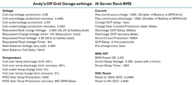
Andy from the Off-Grid-Garrage YouTube channel has done a *lot* of work on charge cycles and charge voltages. This is what he recommends:

Notice that the cell overvoltage is well above the charge voltage target. During changing this allows a cell to go above the target without triggering a cell overvoltage.View attachment 194070

The interesting thing is that he does not turn on balance till the first cell hits the target voltage. He also leaves the charger on for a while to give the balancer time to do its thing. (The Absorption stage should be called the 'balance stage' for LiFePO4) Note: He has pretty much concluded that active balancers with a reasonably high balance current is needed. However, I suspect that if the absorption time is long enough a low current passive balancer could also work.
1707347750078.png
 
I know, you wrote it in your first post 😄
You will have to understand the charging curve of LFP battery.
Anything between 54.4V and 58.4V (3.4v to 3.65V/cell) could mean 100% SOC.
So pick a number and program your inverter.
One disadvantage of charging at lower voltage is the internal bms of each battery could not been able to balance cells.
It's why I suggested you 56 - 57V range.

Thanks for suggestions. Changed the parameters and will wait for sun.

Meanwhile, I have a similar issue in the discharge side as well.

1. I want the batteries to be charged only by PV - So grid/ac charging disabled.
2. When the batteries drained down to a certain level (I used 51v for testing purchase), I need the inverter to be on by-pass mode to supply power loads. So, I set On Grid EOD Voltage(V) to 51v.

This is what happens:

Batteries are powering loads till 51v. As soon as batteries reaches 50.9V the inverter switches to bypass mode as expected. Once it released the batteries, the battery voltage goes up to 51.2 - 51.4v suddenly and then tries to go back to batteries/inverter mode and then voltage drops down less than 51v and goes to bypass. This happens back and forth rapidly (multiple times a second) and unstable endlessly. Is there a way to solve this?
 
Hi @shayamip, I have the same inverter and same exactly batteries in parallel, did you find the settings you like? I am new to all this and confused at this point what to set.
 
I'm using 4x DC house 48v 50Ah batteries in parallel.

According to their specs:
Charging voltage: 58.4v
Operating range: 40-58.4v

1. How should I setup XP parameters according to this?
2. How does the XP keep track of SoC without communicating?
3. Is it possible to limit solar charge at 80% of Soc?

Thank you.
If BMS communication is not possible, you would want to have this in Lead-Acid mode with the Lead-acid Capacity set to the bank.

1710967739242.png
You would then want to set the charge current, charge voltage, and float voltage to spec for the battery.
1710967762049.png
Lastly, you would want to set discharge/charge according to voltage and set the Low DC cutoff for the discharge cut-off voltage.
1710967785991.png

Without BMS communication, the 6000XP will not know the SOC of your batteries and it is currently not available to limit the solar charge.
 
@EG4_Jared - do you guys have a solution for the issue reported by @shayamip ? I'm using closed loop comms with EG4 batteries, so I don't have this issue, but he's trying to use voltage thresholds and having the issue described below:

Meanwhile, I have a similar issue in the discharge side as well.

1. I want the batteries to be charged only by PV - So grid/ac charging disabled.
2. When the batteries drained down to a certain level (I used 51v for testing purchase), I need the inverter to be on by-pass mode to supply power loads. So, I set On Grid EOD Voltage(V) to 51v.

This is what happens:

Batteries are powering loads till 51v. As soon as batteries reaches 50.9V the inverter switches to bypass mode as expected. Once it released the batteries, the battery voltage goes up to 51.2 - 51.4v suddenly and then tries to go back to batteries/inverter mode and then voltage drops down less than 51v and goes to bypass. This happens back and forth rapidly (multiple times a second) and unstable endlessly. Is there a way to solve this?
 
@EG4_Jared - do you guys have a solution for the issue reported by @shayamip ? I'm using closed loop comms with EG4 batteries, so I don't have this issue, but he's trying to use voltage thresholds and having the issue described below:

I believe this has been addressed in the latest firmware. However, if it is still occurring, I would definitely like to take a look at the system.
 
From my understanding, the problem is that these 48V min and 56V max mean nothing since they depend on discharge/charge current.

For example, when you charge at 50 A, you will hit 56v when the battery is 75% Soc where it will be hitting 56V at 95% Soc when you charge at 5A. Same goes with discharging. So, these two numbers mean nothing unless you charge/discharge at the same rate (Amp) everytime.
Yea this is why you're sitting at X voltage for hours instead of stopping the charge entirely. The batteries will stop pulling amps when they're closer to full
Charging isn't a big deal.. and discharge isn't really either since 90% of the capacity won't be involved at that low voltage even with high amp pull
 
Hi @shayamip, I have the same inverter and same exactly batteries in parallel, did you find the settings you like? I am new to all this and confused at this point what to set.

Yes, settled with the following and works without any issue. Things could be optimized bit more. But happy with this atm. Im always using AC bypass to backup when batteries are low. So, my discharge limit is: 48.5v (On Grid EOD Voltage(V))

Lead-acid profile.

Charge voltage: 54.4V

Discharge Cut-off Voltage(V): 44V

@EG4_Jared : Is there way to bump this up to match with On Grid EOD or something closer?

On Grid EOD Voltage(V): 48.5v

@EG4_Jared : Also, to switch back to batteries from AC-bypass, the voltage of batteries has to be on Grid EOD + 3v + correction. Is there way to change the 3V value?. 3V is too much specially if you dont wanna go too low in batteries.
 
Yea this is why you're sitting at X voltage for hours instead of stopping the charge entirely. The batteries will stop pulling amps when they're closer to full
Charging isn't a big deal.. and discharge isn't really either since 90% of the capacity won't be involved at that low voltage even with high amp pull

Sitting on X for long time is not possible with solar sometimes with clouds and the variable load connected to it.
 
Yes, settled with the following and works without any issue. Things could be optimized bit more. But happy with this atm. Im always using AC bypass to backup when batteries are low. So, my discharge limit is: 48.5v (On Grid EOD Voltage(V))

Lead-acid profile.

Charge voltage: 54.4V

Discharge Cut-off Voltage(V): 44V

@EG4_Jared : Is there way to bump this up to match with On Grid EOD or something closer?

On Grid EOD Voltage(V): 48.5v

@EG4_Jared : Also, to switch back to batteries from AC-bypass, the voltage of batteries has to be on Grid EOD + 3v + correction. Is there way to change the 3V value?. 3V is too much specially if you dont wanna go too low in batteries.

If you could DM the serial number for the inverter, I will have to look into the 3v correction.
 
Sitting on X for long time is not possible with solar sometimes with clouds and the variable load connected to it.
we're talking about charging in that scenario so yes floating can be like half a day or even longer in many peoples systems. I'd argue that half of the day is "a long time"
not sure what you're getting at
 
we're talking about charging in that scenario so yes floating can be like half a day or even longer in many peoples systems. I'd argue that half of the day is "a long time"
not sure what you're getting at

In a cloudy day I get 5kw from my panels now and 500wts in next 5 mins and so on...highly unpredictable and changing. Batteries are charging at 60-70amps in 5 mins and...discharging heavily next 5 mins...and so on...I dont know how to get several hours at X voltage or floating in a practical situation like this.
 
In a cloudy day I get 5kw from my panels now and 500wts in next 5 mins and so on...highly unpredictable and changing. Batteries are charging at 60-70amps in 5 mins and...discharging heavily next 5 mins...and so on...I dont know how to get several hours at X voltage or floating in a practical situation like this.
Yea that's a situation to be aware of, there are many situations to be aware of. and... the batteries will still stop pulling amps as they get more charged up, so not sure what you're getting at but not really related to what we were previously talking about.
 
If you could DM the serial number for the inverter, I will have to look into the 3v correction.

1711135847907.png

I am referring this 3V...is there a way to change it by myself?

3v is ok if you let the batteries discharge low SoC.. like say 46v...(for ex..5%) and charging till 46+3v (is like 10%)...no problem

If I want to set the cut of at higher voltage say...50v (ex..30%) 50+3v will be like 80%....So you have to charge the battery like 50% more to get back to batteries from AC-pass thru.

I guess you get what I'm trying to say.
 
Yes, settled with the following and works without any issue. Things could be optimized bit more. But happy with this atm. Im always using AC bypass to backup when batteries are low. So, my discharge limit is: 48.5v (On Grid EOD Voltage(V))

Lead-acid profile.

Charge voltage: 54.4V

Discharge Cut-off Voltage(V): 44V

@EG4_Jared : Is there way to bump this up to match with On Grid EOD or something closer?

On Grid EOD Voltage(V): 48.5v

@EG4_Jared : Also, to switch back to batteries from AC-bypass, the voltage of batteries has to be on Grid EOD + 3v + correction. Is there way to change the 3V value?. 3V is too much specially if you dont wanna go too low in batteries.
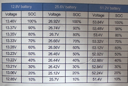
Hi @shayamip , this SOC vs V chart came with those batteries. If we use this chart, wouldn't your setting of 48.5v be too low? It seems the 53.8v to 52.2 (100-20%) is a small range. Mine drops to 52v pretty quickly after using just a small percent of total claimed power, certainly not the ah it is rated at if working within that voltage range. (Unless I am looking at it wrong, I am new to this)

What is your floating voltage set at?

soc.png
 
Last edited:
Hi @shayamip , this SOC vs V chart came with those batteries. If we use this chart, wouldn't your setting of 48.5v be too low? It seems the 53.8v to 52.2 (100-20%) is a small range. Mine drops to 52v pretty quickly after using just a small percent of total claimed power, certainly not the ah it is rated at if working within that voltage range. (Unless I am looking at it wrong, I am new to this)

What is your floating voltage set at?

View attachment 205222

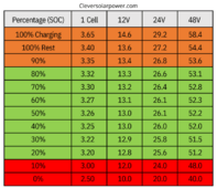
This chart is wrong. I discharged and charged and measured the capacity and they are just above the rated capacity. Use something like below. I Use 53.5v for float to avoid floating.

1711652069186.png
 
Not to get totally off topic but could someone use a shunt that has RS485 and connect it to the XP6000? Something like this below? Basically I use this to connect to monitor my Batteries SOC. Just wondering if it could be used to feed information to the 6000XP as a SOC indicator.

Shunt
 
Not to get totally off topic but could someone use a shunt that has RS485 and connect it to the XP6000? Something like this below? Basically I use this to connect to monitor my Batteries SOC. Just wondering if it could be used to feed information to the 6000XP as a SOC indicator.

Shunt
Yes, you can. . I’m doing exactly that via Pylontech CAN protocol with a Victron Shunt and 6000xp.

Thread 'EG4 6000xp CANBUS Comms with Victron Smart Shunt w/DIY Battery'
https://diysolarforum.com/threads/e...with-victron-smart-shunt-w-diy-battery.80538/
 
Back
Top