Hi Folks,
God bless i found this thread. I was trying to achieve the same thing. Unfortunately I already spent a lot of time trying to make it work with EBYTE E32 RF433 transceivers. I'm unable to make it work so far. Meter COM LED just doesn't come up, despite config on E32 being correct. Does anyone have success with with those?
Or i guess I'll go with already tester method via ethernet. I found that there is also Waveshare to Wifi DIN module available.
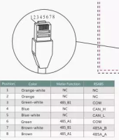
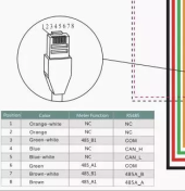
BTW pinout I'm using from RJ45 to unit are pins 3+7 and 6+8 as per wiring diagram. I've tested it with solis directly connected and it works:
God bless i found this thread. I was trying to achieve the same thing. Unfortunately I already spent a lot of time trying to make it work with EBYTE E32 RF433 transceivers. I'm unable to make it work so far. Meter COM LED just doesn't come up, despite config on E32 being correct. Does anyone have success with with those?
Or i guess I'll go with already tester method via ethernet. I found that there is also Waveshare to Wifi DIN module available.
BTW pinout I'm using from RJ45 to unit are pins 3+7 and 6+8 as per wiring diagram. I've tested it with solis directly connected and it works: