diy solar

diy solar

Test run with a small system first?

View attachment 205904

This is my multimeter. not sure which setting I should use.
If measuring voltage you need to move the red lead over to the Volt/ohm port. Also the Volt reading would be for the flat line area instead of the AC cycle (~) image. I find that measuring a panel at the MC4 is fairly easy if you put the red lead in and let it hang as you hold the black lead to the negative. The meter should set on a surface so you don't have to juggle things.

Be careful with working with high voltage! I would start with measuring the terminals on your AIO for voltage and then work back to individual panels to see where the voltage is present. Likely you have a loose connection.
 
Mrs Sandals is not a slave to measuring before cutting as well.

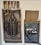
View attachment 205874
There really wasn't much I could do in this space. its really narrow and there is a wire directly above where the cut in the drywall is where the subpanel is. I certainly could have done a better job though. the existing wire may have more slack somewhere in my house though.
If measuring voltage you need to move the red lead over to the Volt/ohm port. Also the Volt reading would be for the flat line area instead of the AC cycle (~) image. I find that measuring a panel at the MC4 is fairly easy if you put the red lead in and let it hang as you hold the black lead to the negative. The meter should set on a surface so you don't have to juggle things.

Be careful with working with high voltage! I would start with measuring the terminals on your AIO for voltage and then work back to individual panels to see where the voltage is present. Likely you have a loose connection.
Ok. So I am seeing 9.45v from the AIO terminals all the way to where I would connect the solar in if I connected anything. I am also not seeing any voltage on any on the panels. guessing that means they are all bunk then. I have it set to the 20 on the DC voltage too.
 
There really wasn't much I could do in this space. its really narrow and there is a wire directly above where the cut in the drywall is where the subpanel is. I certainly could have done a better job though. the existing wire may have more slack somewhere in my house though.

Ok. So I am seeing 9.45v from the AIO terminals all the way to where I would connect the solar in if I connected anything. I am also not seeing any voltage on any on the panels. guessing that means they are all bunk then. I have it set to the 20 on the DC voltage too.
Too low of setting on the DC to read a panel at 37vDC Use the 200v for panels and the 600vDC for array.

ETA: First thing you ought to do is check your meter against a known source like your battery. Place the DC voltage scale at 200vDC. Read the battery. Does it match up with your AIO's reading for battery voltage?
 
Last edited:
Too low of setting on the DC to read a panel at 37vDC Use the 200v for panels and the 600vDC for array.

ETA: First thing you ought to do is check your meter against a known source like your battery. Place the DC voltage scale at 200vDC. Read the battery. Does it match up with your AIO's reading for battery voltage?
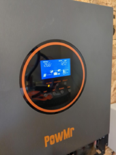
I checked the battery to the AIO voltage and it checks out. the string voltage is 182v. I think i figured out the problem. The AIO came with some MC4 connectors and I think they were either super cheap or I installed them incorrectly
 
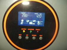
Does your panel resemble this now? Incidentally you can remove the plastic protector on the screen with that little black tab on yours.
 

Attachments

  • P1010009 - Copy.JPG
    P1010009 - Copy.JPG
    183.8 KB · Views: 5
Does your panel resemble this now? Incidentally you can remove the plastic protector on the screen with that little black tab on yours.
Ok. I am now measuring the 182 v all the way back to the AIO. I also measured the amps and its like 7.8. the multi meter sparked everything when I measured it. I followed the instructions on which port to put the + and - wire in the AIO. I am not seeing it in the AIO system. I will restart it.


1711832971190.png

1711832986999.png
 
Good! BTW I notice the lugs on your battery cables seem to be oversized for the AIO's terminal bolts. They usually ship a couple of lugs with the AIO designed to fit. They work with 2 AWG. I prefer pure copper myself (not tinned) and special order them for the 1/4 inch nut size. You might add a larger washer for more contact area if you intend to do any large loading.
 
Good! BTW I notice the lugs on your battery cables seem to be oversized for the AIO's terminal bolts. They usually ship a couple of lugs with the AIO designed to fit. They work with 2 AWG. I prefer pure copper myself (not tinned) and special order them for the 1/4 inch nut size. You might add a larger washer for more contact area if you intend to do any large loading.
I'll have to figure that out later. I just used some M8 bolts I had laying around. I need to finish grounding the system too, so i'm about to turn it off until I can finish working on it later.
 
View attachment 205904

This is my multimeter. not sure which setting I should use.
well I'd start by putting your cables in the correct plugs
I am seeing things all over the place. I am having trouble figuring out how I should measure the voltage or amps because it seems like i can't get a good connection on inside. either that or ALL of the panels are bunk somehow
then continue by measuring voltage like I said, you want 30-37 volt

If measuring voltage you need to move the red lead over to the Volt/ohm port. Also the Volt reading would be for the flat line area instead of the AC cycle (~) image. I find that measuring a panel at the MC4 is fairly easy if you put the red lead in and let it hang as you hold the black lead to the negative. The meter should set on a surface so you don't have to juggle things.

Be careful with working with high voltage! I would start with measuring the terminals on your AIO for voltage and then work back to individual panels to see where the voltage is present. Likely you have a loose connection.
hopefully he's not doing high voltage, cuz he should be doing each one individually lol
 
I checked the battery to the AIO voltage and it checks out. the string voltage is 182v. I think i figured out the problem. The AIO came with some MC4 connectors and I think they were either super cheap or I installed them incorrectly
Yea you got like 30 volts from each panel then
what MC4 do you have that aren't connecting? take a pic of them
were they falling out or something?

Ok. I am now measuring the 182 v all the way back to the AIO. I also measured the amps and its like 7.8. the multi meter sparked everything when I measured it. I followed the instructions on which port to put the + and - wire in the AIO. I am not seeing it in the AIO system. I will restart it.


View attachment 205923

View attachment 205924
cut your wire so it is the correct length for the terminal instead of sticking out so far lol


before you go and flip on/off your solar panels make sure the inverter input is turned off.. or else you cause arc issues as time goes on probably kill your switches
 
You should be using the symbol on the left with V- and 200. That's Volts DC. The red probe wire should be in the other red hole.

Don't worry about amps at this point, the controller will deal with that after it can start talking to the panels.

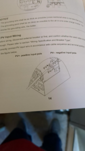
You should see 35-ish volts when you plug the meter into the panel wires. The RED goes in the skinny one, the BLACK goes in the fat one. When you put 2 panels together in series you should see 70-ish volts as the panels add up the volts. A 3rd panel should get you 100-ish volts and so on.

The most common places to have a failure are after the last panel where it connects off to the run back to the inverter. Sometimes a crimp is a little loose in the housing and the pin slides back inside instead of snugly seating. Grab the wires coming out of the joints and smush them together and see if that seats the pins inside.

As you add in panel after panel everything should add up until either you have full voltage or you find a panel/wire/plug that's messed up and causes your voltage to drop to way low volts. That'll be the problem child right there.

If you ever see a dash in front of the volts, double check that you've got the ports in the right place and you've got RED in the +POSITIVE and if you do then that means the plug is backwards.
 
have 12 panels rated at 12V and 100 watts. To have a 12V system,

My only comment is that to build a 12V system, you do not need to limit yourself to 12V panels (which put out 20V actually AFAIK)

Buy used panels that put out around 40Voc and the charge controller or AIO will take care of it. You can still use these panels next year when you change your setup to a 48V battery bank.
 
Ok. I am now measuring the 182 v all the way back to the AIO. I also measured the amps and its like 7.8. the multi meter sparked everything when I measured it. I followed the instructions on which port to put the + and - wire in the AIO. I am not seeing it in the AIO system. I will restart it.


View attachment 205923

View attachment 205924
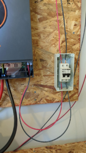
You have the red and black wire in the wrong side on your DC circuit breaker. The red is positive and it needs to go on the right side on the input and output of that breaker. It's clearly marked with a red positive on the breaker.
 
Thanks for all the advice! I have confirmed that all the solar is working now. I have everything turned off right now until I finish wiring up the ground. I may want (or need) to re evaluate how I have some of my wiring going to ensure that its like sorta to code. It wouldn't be a waste to do that because the location I have my solar coming into my house is where I plan on putting an EV charger in the future and i could use the same conduit maybe.

I also learned a lesson on pulling wire through conduit. Its very difficult to pull 10 gauge wire through 1/2" conduit. NEVER doing that again if its more than like 10ft of conduit. lol. I'm doing all this to learn anyways. I may have to open up the building code and just read through it. I'm sure there are places I can find it for free online and im sure there are people on youtube who explain code in detail too.
You have the red and black wire in the wrong side on your DC circuit breaker. The red is positive and it needs to go on the right side on the input and output of that breaker. It's clearly marked with a red positive on the breaker.
I will have to go check that when I get home from work. 😓

You got a separate shut off? lot of old homes around here have them
main on/off and it just feeds the breaker box, sometimes it's outside.
The more I look in my panel, the more it seems like the 60 amp breakers are the main shut off, which is kind of not really a shut off because the two scary braided aluminum wires are still hot. No matter what I do I just assume the whole panel is constantly live.
Aaand I just typed that whole post on my phone completely missing that there was a whole other page where it was all fixed. :fp2
The advice was appreciated, so it wasnt' a waste. lol. I figured out that i had wired the mc4 connectors wrong at the panels.
 
Back
Top