diy solar

diy solar

EG4 Indoor 280Ah 48v WallMount Battery

From the latest (v1.4) manual for the PP outdoor:
/*
• The battery can be installed against a flat wall, but the weight of the battery should not be fully supported by the wall. To help with this requirement, the battery comes with pre-installed feet that should be used to allow some of the weight of the battery to rest on the ground.

• If the battery is installed against a wall, EG4 insists the wall to be made of non-combustible material. If this is not possible, then the unit MUST have a minimum of 2 in. (50.8mm) of clearance from the wall to prevent heat transfer to the wall surface. Also note that whatever mounting solution that is used to grant the 2 in. clearance from the wall MUST be a non-combustible material.

• If installing on flat ground as a standalone unit, ensure there is proper drainage on the ground surrounding the battery to maintain integrity of the module over time and prevent damage from flooding. If installing against a wall, ensure at least a 12 in. gap on each side of the unit for adequate airflow and operations.
*/
Check the latest PP Indoor manual to see what it says, but there’s clearly enough ambiguity above to throw the final decision on the AHJ. 🤷‍♂️
I saw that also. Is it 7" or 12" minimum clearance? The way it is worded. 7" meets fire code. But you need 12" for normal operation. So it sounds like 12" minimum. ???
 
I saw that also. Is it 7" or 12" minimum clearance? The way it is worded. 7" meets fire code. But you need 12" for normal operation. So it sounds like 12" minimum. ???
Apples and oranges.

For the OUTDOOR model you need 12” on the sides to read the display and operate the breaker as they are on the sides.

For the INDOOR model you need 7” on the sides because <Ventilation? Installation? AHJ wants a number? UL required something on the form?>.

If the manual for the INDOOR model specifies clearance on the front you’ll have to determine for yourself what’s reasonable if you aren’t getting it inspected.
 
Does anyone know if the 36.4" height is measured with the feet extended all the way out? Or is 36.4" with the feet all the way in? Maybe the feet could come off?
My roof height is limited
 
2 questions:

1. Pairing this with one 6000XP and the conduit box. Do I need to place a Class T fuse on the battery positive?

2. The battery cables that come with it have the amphenol connectors on one side and then are bare wire (no lugs attached) on the other is that correct? I am just going by the pictures, I don't believe it specifies in writing that I have seen.

Thank you
 
1. Pairing this with one 6000XP and the conduit box. Do I need to place a Class T fuse on the battery positive?
No
The battery and 6kxp, both have breakers built-in.
2. The battery cables that come with it have the amphenol connectors on one side and then are bare wire (no lugs attached) on the other is that correct?
Yes
 
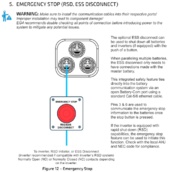
I've been trying to get EG4 to tell me how the RSD function works on the indoor wall mount battery. They seem incapable of answering questions in a usable way. Does anyone here know how the RSD inputs on the battery work? This is needed to pass code for RSD shutdown with my inverter.

In the connection guide:


They have this section:

1715349270378.png

Is is showing the wrong connector layout (looks like the outdoor one, not the indoor one), doesn't detail which connector is the right one (there are 4 RJ45s on the indoor model, not 3), and shows vague single blue lines for connections that don't mean anything for wiring. They talk about pins 3 and 6 but then never explain how they function or what they do.

I've engaged EG4 support for several days now and can't make any progress with them. My email exchanges have been frustrating. I asked:

---
All it says is "Pins 3 & 6 are used to communicate the emergency stop information to the batteries once the stop button is pressed."

Okay, how does it do that?

Do you short pins 3 and 6 to shutdown the battery?

Do you open pins 3 and 6 to shutdown the battery?

Or is this configurable to work either way?

Or do you present a voltage across pins 3 and 6?
---

The replies I have received:

---
Hello,

There is a newer firmware that should include the RSD software, I will link it to you.

Thanks,
Colton
EG4
---

I ask again how the pins 3 and 6 work and which connector to use. The response:

---
If the batteries are fully updated and connected correctly the WALLPOWER PROS should use RSD like normal and work great with the inverter.
Thanks,
Colton
EG4
---

That is no explanation of the function, just reflexive and useless responses.

So, does anyone know how those inputs work? EG4 will apparently be no help, their support people don't seem to know the answer.

This particularly frustrating since I chose the EG4 battery over the Ruixu precisely because it had discreet input RSD functionality and the Ruixu doesn't seem to. But now I wonder if the EG4 actually has it or not.

The lack of clarity and detail in solar product manuals is shocking to me. We are dealing with potentially lethal things and the manuals need to be clear, complete, and precise.

Mike C.
 
I've been trying to get EG4 to tell me how the RSD function works on the indoor wall mount battery. They seem incapable of answering questions in a usable way. Does anyone here know how the RSD inputs on the battery work? This is needed to pass code for RSD shutdown with my inverter.

In the connection guide:


They have this section:

View attachment 214405

Is is showing the wrong connector layout (looks like the outdoor one, not the indoor one), doesn't detail which connector is the right one (there are 4 RJ45s on the indoor model, not 3), and shows vague single blue lines for connections that don't mean anything for wiring. They talk about pins 3 and 6 but then never explain how they function or what they do.

I've engaged EG4 support for several days now and can't make any progress with them. My email exchanges have been frustrating. I asked:

---
All it says is "Pins 3 & 6 are used to communicate the emergency stop information to the batteries once the stop button is pressed."

Okay, how does it do that?

Do you short pins 3 and 6 to shutdown the battery?

Do you open pins 3 and 6 to shutdown the battery?

Or is this configurable to work either way?

Or do you present a voltage across pins 3 and 6?
---

The replies I have received:

---
Hello,

There is a newer firmware that should include the RSD software, I will link it to you.

Thanks,
Colton
EG4
---

I ask again how the pins 3 and 6 work and which connector to use. The response:

---
If the batteries are fully updated and connected correctly the WALLPOWER PROS should use RSD like normal and work great with the inverter.
Thanks,
Colton
EG4
---

That is no explanation of the function, just reflexive and useless responses.

So, does anyone know how those inputs work? EG4 will apparently be no help, their support people don't seem to know the answer.

This particularly frustrating since I chose the EG4 battery over the Ruixu precisely because it had discreet input RSD functionality and the Ruixu doesn't seem to. But now I wonder if the EG4 actually has it or not.

The lack of clarity and detail in solar product manuals is shocking to me. We are dealing with potentially lethal things and the manuals need to be clear, complete, and precise.

Mike C.
What kind of inverter do you have? I know with the EG4 ESS (18Kpv and PP batteries) you wire the RSS button to the inverter, and it uses battery communications to tell the batteries to shut down when the switch opens.

That’s not to say that a switch contact on pins three and six won’t also work. I have the outdoor batteries, but as far as I can tell, the indoor and outdoor batteries only only differ in the housing.
 
What kind of inverter do you have? I know with the EG4 ESS (18Kpv and PP batteries) you wire the RSS button to the inverter, and it uses battery communications to tell the batteries to shut down when the switch opens.
Since my inverter is not an EG4, I am not counting on battery comms to work, or to be reliable enough to depend on for RSD. If the inverter has failed, you still want the battery to turn off under RSD. If you depend on battery comms, then you depend on the inverter in the path. This would be true even if the inverter was an EG4.

That’s not to say that a switch contact on pins three and six won’t also work. I have the outdoor batteries, but as far as I can tell, the indoor and outdoor batteries only only differ in the housing.
I think the design is the same, mostly. The indoor has 4 RJ45 connectors, and the outdoor has 3, so there is something not quite the same there.

All I want to know is how you do RSD with pins 3 and 6 on which connector. Open? Close? Voltage? Something else?

These are simple questions, really.

I specifically paid more for the EG4 indoor wall mount over the Ruixu precisely for this feature. If it turns out this feature is unusable, that will be really annoying.

Mike C.
 
Since my inverter is not an EG4, I am not counting on battery comms to work, or to be reliable enough to depend on for RSD. If the inverter has failed, you still want the battery to turn off under RSD. If you depend on battery comms, then you depend on the inverter in the path. This would be true even if the inverter was an EG4.


I think the design is the same, mostly. The indoor has 4 RJ45 connectors, and the outdoor has 3, so there is something not quite the same there.

All I want to know is how you do RSD with pins 3 and 6 on which connector. Open? Close? Voltage? Something else?

These are simple questions, really.

I specifically paid more for the EG4 indoor wall mount over the Ruixu precisely for this feature. If it turns out this feature is unusable, that will be really annoying.

Mike C.
Well, since the default is going to be for those pins to be open, try shorting them out.
 
Well, since the default is going to be for those pins to be open, try shorting them out.
I will, when I get the battery, though I have to hope this doesn't damage anything. Shorting pins is not an ideal "documentation" activity.

The problem with that is my permit plans have to show the RSD system and how it works. No RSD wiring, no plans, no permit, no order battery, no field test.

Also, any method shown on the plans has to be backed up by documentation in the manual. I can't just say "I tried this and it worked". That's not how professional engineers review plans.

So I need something to document, from the manufacturer, that pins 3 and 6 do RSD when operated in a particular way.

The solar industry seems beset with inadequate manuals that have vague, imprecise, and missing information. For something that is potentially lethal, it should be clearly documented. Clear manuals would greatly reduce returns and support effort, too. Skimpy there is penny wise and pound foolish.

Mike C.
You’re not wrong, E4 seems to have great hardware, but their documentation is a bit mixmastered and copy/pasted between their different inverters and batteries, and it makes them difficult to use.
Also, they appear to have farmed out their firmware to Elbonia (if you see what I did there), and figuring out what cable to plug into what port and what app to use at what baud rate at what switch settings to upgrade the firmware between a revision that you can’t tell and another revision that you can’t tell is a bit of a nightmare.
 
I saw a video on youtube from them where they said it faults the BMS some how. Not super helpful but it worked in conjunction with the inverter from what I gathered. They do have several employees on here so maybe one can describe how it works.
 
They do have several employees on here so maybe one can describe how it works.
I am hoping.

I've already done the direct contact with EG4 support for the last 5 days without making meaningful progress.

Ultimately, I may just have to buy one, try it, and document it myself (and I'll post it here, of course). Not ideal.

The real bummer would be if the RSD pins don't actually do anything.

Mike C.
 
Also, they appear to have farmed out their firmware to Elbonia (if you see what I did there), and figuring out what cable to plug into what port and what app to use at what baud rate at what switch settings to upgrade the firmware between a revision that you can’t tell and another revision that you can’t tell is a bit of a nightmare.
I sure hope the RSD pins do not depend on firmware. They should be some sort of direct to the MOSFETs shutdown.

If firmware is involved in the RSD pins, then getting EG4 to document the functionality is even more critical so they shouldn't change it with some future firmware update.

Most RSD systems are NC (normally closed) types such that a failure of the circuit renders the system safe. If this is a NO (normally open) type, that means I need to get a double pole E stop button to handle that.

I'm kind of hoping it is a voltage input. The inverter has a 12 volt rail that goes off when in RSD and maybe I can tie that to the RSD pins. Again, without clear docs, it is a bit of a risk and reverse engineering it takes time and care.

Mike C.
 
I am hoping.

I've already done the direct contact with EG4 support for the last 5 days without making meaningful progress.

Ultimately, I may just have to buy one, try it, and document it myself (and I'll post it here, of course). Not ideal.

The real bummer would be if the RSD pins don't actually do anything.

Mike C.

I apologize for the confusion. The Ethernet cable pins 3 and 6 should be connected to the open battery communication port of the master battery to NO. I will contact our technical writing team to look at improving this section of our manuals and reference sheets.
 
Back
Top