diy solar

diy solar

Source to buy quality wire ferrules?

I have mixed feeling in ferrules, and mostly my impression is that they mostly help make up for poor connector designs.

I've been doing alot of wiring lately, and there's a very wide range of ways to make screw-type and press-in connectors. I wish there was more of an industry standard make it less of an issue.

I generally like the terminals on good-quality breakers that have a curved metal band that generally conforms to the shape of a round wire to provide maximum surface area, and is drawn up to tighten around the wire. I just wish they would move away from the slotted screws heads that are just horrible.

This one has to take the cake, though: https://www.amazon.com/gp/product/B0C9TM4KLZ

They have two inputs and two outputs, but a single screw in each. They also clearly show multiple pictures of red wires being connected in one side, and black wires being connected on the other side, but both sides are connected! They work okay to splice a single connector (one on each side), and you can use them to create a T, but that requires interleaving the wires under one screw, which I don't trust.
 
My choices in using ferrules depends on whats clamping down on the wire only.

If its a caged or boxed arrangement and the screw is apply pressure on the backside of the cage to compress it on to the wire then no ferrules.

If its a screw end will be actually going down onto the wire strands themselves I use ferrules.

To me it just seems common sense. The ferrule makes contact 360 degrees around the wire end. This in turn will cause more of the wire strands to have connection with the conductor area aka more strands are taking part in the connection process.

The screw end only contacts a give area pressing it against the conductor plate. Only the strands that happen to get caught between the screw end will have any contact with the surfaces without a ferrule.

Common sense isn't always right of course. But its a good start :)

That pretty much mirrors my assessment of them making up for poor connector design. If a connector is designed to accept a wire (stranded or solid), it aught to be designed to mate with it appropriately. A ferrule is not much different from a solid wire end, which is fairly easy to mate with reasonably, but many connectors fail with stranded. Stranded can better mold to the connector shape if it's designed right, but some are not.
 
I have mixed feeling in ferrules, and mostly my impression is that they mostly help make up for poor connector designs.

I've been doing alot of wiring lately, and there's a very wide range of ways to make screw-type and press-in connectors. I wish there was more of an industry standard make it less of an issue.

I generally like the terminals on good-quality breakers that have a curved metal band that generally conforms to the shape of a round wire to provide maximum surface area, and is drawn up to tighten around the wire. I just wish they would move away from the slotted screws heads that are just horrible.

This one has to take the cake, though: https://www.amazon.com/gp/product/B0C9TM4KLZ

They have two inputs and two outputs, but a single screw in each. They also clearly show multiple pictures of red wires being connected in one side, and black wires being connected on the other side, but both sides are connected! They work okay to splice a single connector (one on each side), and you can use them to create a T, but that requires interleaving the wires under one screw, which I don't trust.
I use these all the time. UL listed and insulated. Passes inspection. Uses a hex security screw head. Contains dielectric grease. Allows splicing side by side or end to end by use of both ports.


I buy them from my local electric supply house.

The ones in the amazon link appear to be non UL approved knockoffs.
That makes sense, that this connector is intended to be used either as a butt-connector, with one wire on each side, side-by-side. A combination of the other two types of connectors.

The problem is the Amazon ad that has pictures like this, which seems to show both a straight butt-splice, and feeding the connector with both a red and black wire:

1700838313003.png

They do seems to be well built, and work well in the intended application, but they're pretty chunky.
 
What's a ferrule? :p

Seriously , I would never consider using ferrules on the MPPT. I don't know the name for those types of terminals, but they effectively maximize contact area between the terminal and stranded wire. Putting a ferrule in them would reduce contact area.


1.2. Wiring safety precautions • Use flexible multi-stranded copper cable for the battery and PV connections. • The diameter of the individual strand of the cable used should not exceed 0.4mm (0.016 inch) or have a surface area exceeding 0.125mm² (AWG26). • The maximum operating temperature is 90°C (194°F). • • A 25mm² cable, for example, should have at least 196 strands (class 5 or higher stranding according to VDE 0295, IEC 60228 and BS6360). An AWG2 gauge cable should have at least 259/26 stranding (259 strands of AWG26). Example of suitable cable: class 5 “Tri-rated” cable (it has three approvals: American (UL), Canadian (CSA) and British (BS)). • In case of thicker strands the contact area will be too small and the resulting high contact resistance will cause severe overheating, eventually resulting in fire. See below figure for examples of what cable to use and not to use.
View attachment 142745


I would say this is consistent with Guy's assertion.
Am I to believe that the 10ga, 19 strand PV wire, commonly sold and widely used is of insufficient stranding?
 
That makes sense, that this connector is intended to be used either as a butt-connector, with one wire on each side, side-by-side. A combination of the other two types of connectors.

The problem is the Amazon ad that has pictures like this, which seems to show both a straight butt-splice, and feeding the connector with both a red and black wire:

View attachment 179483

They do seems to be well built, and work well in the intended application, but they're pretty chunky.
They are not designed to have one wire in and 2 out for that model. The set screw will really only hold down one wire properly and then you put the caps on to protect from moisture. However, I suggest that for anyone looking, they go to the NSI website, search the Polaris catalog of parts. There you will find all of the models they make including complete distribution models like 1 wire in and 5 out.
 
Last edited:
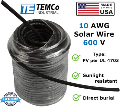
Would have to examine that, wire is from Temco, their PV line. Looks to be between 22 and 23 ga., .0234" diam.


ETA: Even their 8 ga is between 24 and 25ga, .0185".

Then it looks like you have your answer. I personally don't worry about it on the input line because PV current is typically well under max. I've run 10awg "PV" wire directly into the unit, but that wire was nowhere near 30A... maybe 7-8A.

I currently run typical "PV" wire, that likely doesn't comply, into a MNPV 15A breaker with superworm 8awg (which definitely complies) from breaker to MPPT. On the output side to battery, I have 8awg superworm, which complies. Once the full array is deployed, I will have fine strand 2awg welding wire in and out of the 250/100.
 
Solder is soft and the connection will become loose in time and also with heat.
 
I use wire ferrules on the ends of my 10 awg PV wire and 10 awg THHN wire. Makes them easy to make sure none of the strands get bent when making connections and tightening them with a screwdriver or latching down. HOWEVER, ferrules really serve to keep the wires together when inserting and tightening down. The ferrule is easily deformed by a screw or compression terminal. So consider that if you are removing them in and out, they may get smashed down and not be easily put back in in which case you need to cut off the end and install another ferrule.
 
Just last weekend I was redoing my MPPT wires. The ferrules had smashed and I couldn’t get them out to the Victron. To the point where took a chance on breaking it. I’m off ferrules for that connection.
 
Back
Top