diy solar

diy solar

New 10kw NHX AIO From Watts247

Don't think that is due to resistance, rather to discourage disconnecting.

Keep existing ground configuration. Consider bonding also to any gas and water pipes. Jumpers around any dielectric union.
Our utility wants the bond to gas pipe some distance from the meter and its vents. Wonder why?? It threw a spark when I touched ground wire to it.
I think gas pipe provides a parallel connection to neutral wire between houses.
 
Sounds like this is also ok. Removed the ground wire from main panel directly to ground rod. That ground wire now runs from the main panel to a ground buss bar in the combiner box, then on to the ground rod.

One wire short of running ground in the way described in post #275. If below is fine, it saves the headache of trying to push another conductor through 26' of crowded conduit.

If it's not ok, I'll find a way to get another wire in there.

View attachment 212175
No, ground rod has to be at N-G bond location which is first disconnect.

What is this combiner box? Just a junction for grid power input?

Ground loops can cause RFI, be aware of the loops.

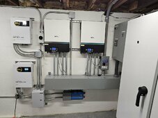
If you use a wiring trough or large conduit and run all the wires to and from each inverter, only one EGC is required. EMT conduit from a trough, for example in this photo, doesn't require an EGC as the conduit is the grounding path. I do however run a single EGC to the inverter to ensure it is grounded well.

Inverters and charge controllers.jpg
 
Wanted to do a trough as everything looks so clean, but it just didn't work out.

No gas lines or metal water pipes.

Thanks guys.
 
Ground loops can cause RFI, be aware of the loops.


View attachment 212221

Wiring trough connects to inverter #1 connects to U-channel connects to inverter #2 connects to wiring trough.
That's a loop in ground, correct?

Nothing wrong with a mesh ground in my book. I don't think there is any harm in connecting ground across so it forms loops.
(Except in my world, where individual electrons drift through a vacuum, and chassis current even at 60 Hz makes magnetic field which applies force to the electrons.)

I think "ground loop" matters if "ground" is used as voltage reference for analog/RF signals, or low level digital signals.

A loop (current antenna) or stub (voltage antenna) only radiates EMI if excited with current or voltage. Which isn't supposed to be flowing in ground. EMI filters will shunt some EMI currents to ground, but so long as "loop" of that ground and whatever conductor are coaxial or twisted, current will follow that low inductance path and not radiate.

I don't want higher frequencies traveling in L or N, then back through a ground wire that follows a different path.
 
Can the MPPT's be paralleled? I've got one string of 10 panels that I need to put up, The ISC is between 17-18 amps, before bifacial gain. I don't think there will be much at all, because they will be roof mounted.
 
According to page 53 of the manual, there is an option to parallel the PV inputs.

The tech specs show that the PV current max is 14 amps though.
Most of the newer larger panels run about 48 to 49V for VOC and Isc under 12A. I know my 530W JA Solar are around 13A and glancing at the spec sheet for the 370W NE Solar are 11.42A.

@aero83 you need to put up your panel specs.
 
Most of the newer larger panels run about 48 to 49V for VOC and Isc under 12A. I know my 530W JA Solar are around 13A and glancing at the spec sheet for the 370W NE Solar are 11.42A.

@aero83 you need to put up your panel specs.
These are 650w bi facial ones that I got for 10x @$100ea the isc is 17.xx. I'll get the specs when I get home.

The 14a rating of the inverter is why I'm asking about paralleling mppts.

I'm trying to decide between thtis NHX and a a couple of SRNE options. The SNRE has mppts that match better with the 650 panels.

I've got a situation where the solar will go on and in a shop about 120ft from the main panel in my home. I don't want to do net metering. I want some battery, due to large amount of short term outages.

So backfeed the panel with cts for zero export with a hybrid inverter, and a critical loads panel for the important loads. Or a parallel srne 10k, and have all power go through the inverters without back feeding main panel.


The home is all electric, GSHP, well, induction stove, water heating, no access to gas.

Peak I've ever seen is about 15kw.


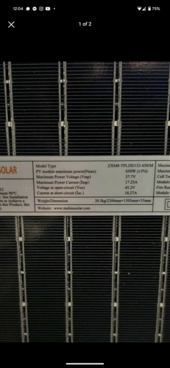
Edit: apologies, I was using isc, it's 17.25 imp, 18.2isc. 37.7 vmp. 45.2 Voc I have attached a picture of the data plate.
 

Attachments

  • Screenshot_20240501-120406.png
    Screenshot_20240501-120406.png
    479.8 KB · Views: 4
Last edited:
Run them in parallel for 300 amp, he says ...

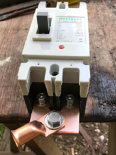
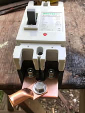
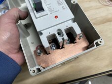
It's a good thing I don't throw away scrap pieces of copper. Guessing this should work.

View attachment 212624

I would like to see manufacturer's data sheet.
In particular to find out if it is polarized, and polarity of each pole.
Also, NRTL ratings (if any)

The part number doesn't show up in a search, and is suspiciously related to vendor's name. I'm thinking it may be labeled for them.

 
These are 650w bi facial ones that I got for 10x @$100ea the isc is 17.xx. I'll get the specs when I get home.

The 14a rating of the inverter is why I'm asking about paralleling mppts.

I'm trying to decide between thtis NHX and a a couple of SRNE options. The SNRE has mppts that match better with the 650 panels.

I've got a situation where the solar will go on and in a shop about 120ft from the main panel in my home. I don't want to do net metering. I want some battery, due to large amount of short term outages.

So backfeed the panel with cts for zero export with a hybrid inverter, and a critical loads panel for the important loads. Or a parallel srne 10k, and have all power go through the inverters without back feeding main panel.


The home is all electric, GSHP, well, induction stove, water heating, no access to gas.

Peak I've ever seen is about 15kw.


Edit: apologies, I was using isc, it's 17.25 imp, 18.2isc. 37.7 vmp. 45.2 Voc I have attached a picture of the data plate.
You should contact Ian, he might have tested the max Imp he put thru the charge controllers and it might be slightly higher than what the manual shows.

As long as you don't exceed max VOC with low temperature coefficient factored in, the charge controller will just clip the incoming amps. This is over paneling and doesn't hurt anything, it just limits how much power can be pulled from PV. 3A at 450V is 1350W loss at peak power, however you can pull max input for longer during the day and on cloudy days get some extra input from PV.

I'm not a big fan of over paneling but in your case it might be fine. Be aware you are losing 1350W at peak power, not a big deal with one string but with 4 strings that is 5400W for probably an hour at peak sun (5.4 Kwh). However you can get those watts before and after peak sun for longer.
 
I would like to see manufacturer's data sheet.
In particular to find out if it is polarized, and polarity of each pole.
Also, NRTL ratings (if any)

The part number doesn't show up in a search, and is suspiciously related to vendor's name. I'm thinking it may be labeled for them.

Didn't have any luck finding the source of this breaker but it looks a lot like these https://www.ebay.com/itm/225501204603?var=524524401221

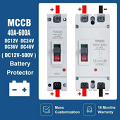
and any time the posts are labeled, it makes me wonder if the breaker is polarized.
 
That is EXACTLY what I was looking for, and concerned about.

If you parallel 2 poles, one carrying current in the correct direction to interrupt the arc and the other one backwards,
When the breaker trips the correctly oriented one interrupts. All current hen goes through the backwards pole which fails to interrupt.

Can't find a data sheet for "TXCM1-B250" either.

Oh, (+) and (+) on two ends of a pole doesn't mean polarized. Seems to be a suggestion to interrupt both positive and negative.
Need to see manufacturer's specs.

1714667174921.png

1714667208694.png
 
Once again getting an uneasy feeling.

This was Ian's response when asking how to wire this two pole 150amp breaker for 300amps, " ...
No both those drawing show poles in series, we want to wire both poles in parallel Red + on both poles, the negatives wires directly to inverter bypassing the breaker, ... ".

Have class t fuses on everything but really not wanting test any of them.


.
 
I just used one side of the 200 amp breaker. But I think the unit pulls 210amps. So the 300 amp requirement makes sense.

The copper you added looks fine. You definitely wouldn’t add the negative to the breaker.
 
The manual recommends a 300 amp breaker but states 190/210amp charge/discharge. Same with output of 46amps but recommends a 63amp breaker. Headroom for nuisance trips? Not too hard to find a 250amp breaker, but a 300, not as easy.
 
The manual recommends a 300 amp breaker but states 190/210amp charge/discharge.
What exactly is this breaker for?

Same with output of 46amps but recommends a 63amp breaker.

SRNE is the same, the output is 5000W per leg with a 7500W surge rating. 7500W divided by 120V = 62.5A

Headroom for nuisance trips?

Yes, for the surge. Wire also needs to sized accordingly.
Not too hard to find a 250amp breaker, but a 300, not as easy.
 
That is EXACTLY what I was looking for, and concerned about.

If you parallel 2 poles, one carrying current in the correct direction to interrupt the arc and the other one backwards,
When the breaker trips the correctly oriented one interrupts. All current hen goes through the backwards pole which fails to interrupt.

Can't find a data sheet for "TXCM1-B250" either.

Oh, (+) and (+) on two ends of a pole doesn't mean polarized. Seems to be a suggestion to interrupt both positive and negative.
Need to see manufacturer's specs.

View attachment 212848

View attachment 212850
I always thought the breaker from Watts247 was this DIHOOL https://www.amazon.com/dp/B0CLQS9SN...trial&sp_csd=d2lkZ2V0TmFtZT1zcF9kZXRhaWw&th=1

I'd rather have the later version, here is 320A. https://www.amazon.com/dp/B0CJBBDMM...sc=1&coliid=I140PIT8GG3WS0&colid=IJC9RMFZ4T07
 
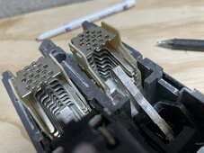
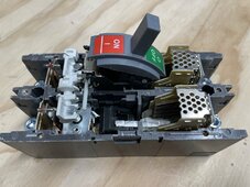
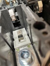
I’ve opened up the Watts24/7 200 amp version. I was curious about polarization and I found out that both sides were symmetrically exact. That being said I don’t know if top or bottom is best for positive. There are huge arc chutes, thermal and magnetic interrupts. By design the moving contacts change state very quickly and gets out of the way so the arc doesn’t get much time to damage contact material (silver alloys?). My take away is it is very well made with one potential issue and that is the terminals. The cap screws (provided) thread into copper so common sense should be used when tightening. They felt firm when attaching a copper buss like Kornbread did above. I have no idea who actually makes these because they seem to be rebadged, cloned or copied. And no clue if they are internally similar.
My opinion is they are probably overkill for our 16S 56V needs regardless of polarization as big as they are. The smaller DIN breaker are another story and observation of polarization on these is absolutely paramount and potentially dangerous, especially if not heeded at PV voltages. I used mine for the battery disconnect service and for preservation of contacts, I only open the contacts when I’ve reduced the load and would not be overly concerned about disconnecting in an emergency. The buss across the bottom ties the breakers together and is also where all my batteries come together. The top of the breaker is independent and branches to each inverter. That way each inverter is breakered at 200, not 400 amps and any either pole can trip both sides. Since the breaker top is isolated when open I used two diodes to each terminal and to a pre charge resistor.

IMG_0479.jpegIMG_0474.jpegIMG_0476.jpegIMG_0506.jpeg
 
Back
Top