diy solar

diy solar

House burned down

I am sorry for your loss. Just to clarify for other readers and emphasize what others have said, the cause of the fire was the arcing from the fuse not the LFP battery.
My concern is what caused the fuse to do it's job? If he had a clean install, was it a bad cell?
I'm pretty sure I did a very clean job building my batteries, but can't help being concerned. Every time this sort of thing happens, I'm always anxious to hear the root cause to know I didn't make that mistake.
 
I am sorry for your loss. Just to clarify for other readers and emphasize what others have said, the cause of the fire was the arcing from the fuse not the LFP battery.
Can we think this thru just a little bit?

The fuse blew, ok. Did it blow in a half asked way that was unsafe or did it work as intended? If it blew as normal, and if an arc formed, it would vaporize the remaining metal and go out in short order.
 
Just couple notes not necessary specific to the OP system to use this opportunity to help prevent future losses from others:

  • - Don't build your system assuming there will never be a "catastrophic" event. What I mean by this is if a component fails in your system it will not cause a cascading effect.
    • Biggest offender I've seen here is people putting LifePO4 cells on inappropriate shelving.
      • They should NEVER be put on wood shelving as not only can this sag from getting wet (or leaking electrolyte even) but it is flammable! If a battery on shelf below starts burning will it be able to take out all the other batteries on shelves above it because the shelving is made of flammable material? Can top shelf If it catches on fire start the ceiling of the room it is in on fire?
      • Don't use those wire shelves that require clips to keep the entire shelf from falling out between the horizontal bracing.
    • Did you follow manufacturers recommendations if it says to not mount the component on a flammable substrate? I've seen quite a few installs mount onto plywood when I know the installation instructions for that component says to mount on non-flammable substrate.
    • Make sure you have built your DIY battery safely. Clean looking, cell casings electrically isolated, etc.
  • As other's have mentioned there is a lot of concern even about Victron using fuses that have a very low AIC. A LifePO4 battery should always have over current/short circuit protection that can handle at least 10k AIC and preferably 20k AIC or more. This is readily achievable with T-fuses or MCCB breakers rated appropriately such as those from Noark.
  • Have smoke detector directly over battery bank.
  • Have fire extinguisher nearby battery bank so that when smoke detector does go off you may be able to do something about it.
 
I was under the impression they (LiFePO4) would not do this. Too bad.

Note that there is a big difference between thermal runaway and igniting venting electrolyte. In the latter, if you take outside oxygen away, the fire goes out. In the former, the thermal runaway reaction creates its own oxygen. This oxygen comes from the Cobalt Oxygen bond, and this one is rather weak. The Iron Phosphate (PO4) bond is much stronger. Both electrolytes in both chemistries release flammable gasses (most notably Hydrogen) when venting.
 
Note that there is a big difference between thermal runaway and igniting venting electrolyte. In the latter, if you take outside oxygen away, the fire goes out. In the former, the thermal runaway reaction creates its own oxygen. This oxygen comes from the Cobalt Oxygen bond, and this one is rather weak. The Iron Phosphate (PO4) bond is much stronger. Both electrolytes in both chemistries release flammable gasses (most notably Hydrogen) when venting.
I think some here have configured exhaust fans to turn on upon possible battery shenanigans to keep venting flammable gas below ignition levels. I guess not far removed from venting hydrogen from lead acids.
 
The leaking, bulging cell…

Was it left in the system?

Could that cell have just totally failed, and gotten all the other banks dumping current into basically a shorted cell?
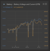
Since this is a Victron system that was reporting to Victron's cloud based VRM Portal there may be some evidence to support this there if looked at it more detail. You can create a custom graph of just the smart shunt for instance and show precisely the current and voltage going through the smart shunt.

@Jejochen I realize you have much more important things to contend with but in case you did not know the VRM portal may provide more data on what may have happened. The normal graphs provided don't provide much detail but in sidebar if you go to "Advanced" you can create a detailed graph of the data for the battery assuming you had a smartshunt. Example below of one of the graphs you can create:
Screenshot 2024-04-29 at 10.18.24 AM.png
 
Last edited:
I just happen to have a class T fuse and a 4 wire milliohm meter downstairs. I'll check the resistance in the morning to see what it says.


OK, here are the results of the fuses I happen to have laying around - all values in ohms - 4 wire 1035+ meter

Class T 300a = 0.00025
Class T 200a = 0.00040
ANL 250a = 0.00054
MRBF 200a = 0.00043
 
The leaking, bulging cell…

Was it left in the system?

Could that cell have just totally failed, and gotten all the other banks dumping current into basically a shorted cell?

The OP posted in that thread that he replaced all the bad cells in/around the leaking one. That was also from 2021 if I remember the date right. The only take-away I get from that picture is there appears to be no spacer between cells and sitting directly on cement board.

The OP redid the enclosure using a custom metal one and it appears the shelf it is sitting on is now just metal. I can't tell if it is insulated or not.
 
Those measurements are assumed to be at 25 deg C with no current flow. Thanks
I would expect the resistance to increase with temperature.

Agreed - in this case they are spares in my house at 72F so just a bit below standard. They are just laying on the bench and not in circuit so no current.

I'll hook up and turn a heat gun on the class T and retest when they hit 120f just to see if there is a change.

Scratch that - I'll put some in holders and run 150amps through them one at a time and watch the voltage drop across them change over time if it does. The heat gun wouldn't mimick the actual heating from current since it would be heating from the outside in verse heating the fuse element from the inside out.

And monitor the temp with a laser.... Wish I had a thermal camera. .... This will have to wait until I have time probably not this weekend but the next.
 
Last edited:
Hmm, i don't see why they should be the same. I have cutting board sheets between to prevent conduction between cells. I have cement board below because it is fireproof and sits on a 2x12 shelf.
The empty rack mount style cases seem to have the bottom lined as well but I guess that makes sense as it's steel.
 
Hi guys
-as already said, i can only post once in a while as i have a lot of other stuff going on right now
-when i was building my system, dividers between cells was not a thing yet. The thing back then was clamping cells or not. The cells have no spacers between.
-i will not participate in guessing games, my mind is not into that now, just want to give the facts.
-the cells were sitting on high density non conductive fibre boards, and metal parts of the rack got fibreboard as shieding to minimise contact issues
-dodgy heatshrink...i mean common, of course the back was cut off and completly free. If that was aan issue, it would have happened way sooner. The system was perfect for 4 years or so.
-and yes, of course i swapped the leaking cell.
-when i have a little spare time, ill pull the victron numbers
 
Hmm, i don't see why they should be the same. I have cutting board sheets between to prevent conduction between cells. I have cement board below because it is fireproof and sits on a 2x12 shelf.

I think my objection would be that the cement board is rough and no matter how they are compressed they will move a fraction of a MM/inch as they cycle. Over time I think that would eat through the film and depending on the cell it might eat into/through the battery case as well. Obviously over a period of years, but we expect 10~15+ years of the system
 
I think my objection would be that the cement board is rough and no matter how they are compressed they will move a fraction of a MM/inch as they cycle. Over time I think that would eat through the film and depending on the cell it might eat into/through the battery case as well. Obviously over a period of years, but we expect 10~15+ years of the system
I used HPL, its as smooth as a mirror
 
I am sorry for your loss. Just to clarify for other readers and emphasize what others have said, the cause of the fire was the arcing from the fuse not the LFP battery.

Note that there is a big difference between thermal runaway and igniting venting electrolyte. In the latter, if you take outside oxygen away, the fire goes out. In the former, the thermal runaway reaction creates its own oxygen. This oxygen comes from the Cobalt Oxygen bond, and this one is rather weak. The Iron Phosphate (PO4) bond is much stronger. Both electrolytes in both chemistries release flammable gasses (most notably Hydrogen) when venting.

The leaking, bulging cell…

Was it left in the system?

Could that cell have just totally failed, and gotten all the other banks dumping current into basically a shorted cell?

Did the fuse sustain an arc and ignite combustible material?

Or did the cell fail, get backfed so it over-charged and vented, and is backfed current in that case sufficient to blow fuse?
If so, fuse is not explosion-proof and would be source of ignition.
 
Back
Top