diy solar

diy solar

MC4 connectors a massive scandal

I would not recommend them for high voltage. You can squeeze in some dielectric grease to help with voltage leakage and corrosion. It will run though if they get hot enough.

I had actually contemplated them at one point but I live in a very moist environment and even with grease, they would corrode. All my strings are low voltage and low power. Its not a good choice, but then again, I have used wire nuts on speaker wire for a small temp system once....


See, I am thinking clean wires and a marine grade heat shrink with adhesive inside is the way to go. It is made for this sort of thing. And I don't mean the no-name stuff of amazon, like lugs, crimp tools, bus bars, and MC4 connectors there are many cheaper fakes that don't live up to their claim.


I've had many mc4's fail and melt. But then again I'm always mixing various mc4 connectors on various products. You never know what you're going to get

Life is like a box of MC4 connectors - you never know what you are gonna get. (said in my best Forest Gump accent)
 
I have done some crimped butt connectors, both with the heat shrink already on them, or non-insulated add your own heat shrink, and either way i am dubious about it because the 'jacketing' you're left with is much thinner and imo less UV-resistant than the insulation on 'factory' PV wiring. I consider it a weak spot when i make those connections, personally. Not that it wont hold up if left alone in darkness, but doesn't offer the same level of durability or protection as a 'functional' MC4 connection.

I have run into poorly-matching MC4s, but i blamed it on me buying the cheapest shit imaginable. I know paying more isn't a guarantee either but i didn't feel qualified to declare it a huge issue since i hadn't tried a bunch of brands at different price points. I consider it more of a cheap shit from China issue vs an MC4-specific thing.

Ive run into several melted MC4s in my setup. Mostly the cheap crap i bought. But one thing i always do is use dielectric grease because ive realized not only does dielectric grease keep away oxygen (thus oxidation), but it also works to thermally conduct heat away from the trouble spot more effectively than a 'dry' joint. Making little heat in a tiny spot with no way out = escalating temps until something melts. Making the same amount of heat but then dispersing it throughout the connection and nearby wiring = whole thing gets warm but nothing melts. It doesn't exactly fix a connection being bad from the start, but it does allow a connection to be worse without actually melting!
 
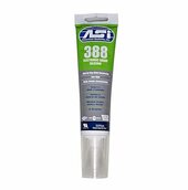
Use the silicon designed for electrical connections... I have a tube now and it has worked great ..

The standard stuff will corrode copper wire and part… just the off gassing will corrode copper if in tight quarters.
Thanks, good to know there is a specific silicone for copper!. I believe the clear cheap stuff is the worse.
 
It was the wrong picture but the correct company ..my internet has been off and on since yesterday and I couldn’t acquire the proper link..it’s been weak all morn....

you are correct as they are for the most part the post male/ female joint , but I do use the ring terminals on occasion for smaller wire..

Been using them for many years never the first problem .
Guys these are the standard "Lucas" pattern push fit connectors widely used in the auto industry for decades. However beware Chep Charlie, he makes these out of thinner metal so they dont maintain the spring force between blade and female socket.. Check your self to see the difference.
In principle these are very good but only go to 20A (6.3mm blade). However there is a 9.5mm blade version (yellow) but you can only get it in FEMALE. The industry only expected these to be used on equipment ie connecting a dynamo. Good for 40A maybe. I have a collection of these Ebay). Sorry not allow to mention here. I use the uninsulated crimp pair versions together with crimp/solder (at core tip - dont let it wick down the cable) then apply glue heatshrink. a silicon tube shroud can be fitted over the coupling with si grease. Pulls apart easily for occasional maintainance. Its old school and you can inspect it - unlike rubbish MC4s

But thats my 10c YMMV
 
  • Like
Reactions: JRH
Guys these are the standard "Lucas" pattern push fit connectors widely used in the auto industry for decades. However beware Chep Charlie, he makes these out of thinner metal so they dont maintain the spring force between blade and female socket.. Check your self to see the difference.
In principle these are very good but only go to 20A (6.3mm blade). However there is a 9.5mm blade version (yellow) but you can only get it in FEMALE. The industry only expected these to be used on equipment ie connecting a dynamo. Good for 40A maybe. I have a collection of these Ebay). Sorry not allow to mention here. I use the uninsulated crimp pair versions together with crimp/solder (at core tip - dont let it wick down the cable) then apply glue heatshrink. a silicon tube shroud can be fitted over the coupling with si grease. Pulls apart easily for occasional maintainance. Its old school and you can inspect it - unlike rubbish MC4s

But thats my 10c YMMV

The only thing I use these connections for is a low voltage ,low amperage system connections on the arrays…

These are very good quality connections…
how well you crimp ,install and maintain them can affect their longevity, performance and effectiveness ..( as in everything else you assemble)..

I have installed hundred on boats in a salt water environment for a living…without a single failure ..

If they are waterproofed , they work perfect… easily maintained, or unfasten and refastened or replaced if desired …. Different jobs requires different prep and technique..

On my solar I use the stripped bare 10 ga wire ends hardwired at the combiner box. All PV strings to combiner box are the same length. 8 FT.

The yellow connectors I use a 30a max rating , I typically aim for a half load for wires and connectors on everything I do when possible .
All of my series strings are 6 amps or 13 amp when they arrive and go into to parralell at the combiner box ,we’ll below the half load rating , as I said.
I don’t use these connectors past the combiner box….

The wires from the combiner to the system are 6 ga- 2 ga- 1/0 & 4/0…..they are lugged and crimped

The yellow connectors are rated at 600v while all of my arrays are only 70v to 100v…then reduced by the CC to supply a 24 volt system

When doing the voltage drop testing I do on each section’s connection it was basically non- existent at the array …they are excellent connections…

From the combiner box to the CC ( 1/0 cable) it does lose less than half of 1 % ( 0.5%) on the 65 ft run back to the CC area after being combined.

The array connection temps and all wires were all consistently very good…at full power .

Finally I like the fact that they are somewhat translucent…with a good light and pair of glasses..it’s easy to see a color change happening ….or see if corrosion is snooping around the connections..

I know many disagree , but I trust these far more than a mc4 …

But that’s just my opinion.J.
Yep JR that sums it up very well (dump the MC4s)

I like the idea of sharing load current, split it into say 50% paths, dont go loading connectors to max. (eg 2 x 20A paths are more benign than 1 x 40A path - cos heat = I^2*R and the devil is in your contact resistance.
I also like the idea of using transparent covering sleeves (so you can inspect the coupling for signs of stress).
Also use liberal silicon grease around the joint

its just my old school training.
 
  • Like
Reactions: JRH
How best to check the mc4 connecters? Take the screw cap off and check the resistance? Infra-red gun?
 
Back
Top