diy solar

diy solar

Magic Smoke came out......... ##it happens

You are using 10ga wire for pv over a very long run?
Wow. @Zwy
Could what @D71 said be related to your problem?
I was originally planning to do 100 yard runs to my panels and was told I would need 8AWG to keep voltage loss to within acceptable levels at that distance, and I'm running lower voltage than you are. Long strings of 8AWG was too expensive I abandoned the idea.
But if you're running 10AWG over long distances at pretty high voltage. Maybe it's causing wire heating issues for you?
It will be most obvious at connections where resistance is higher. Why we ran straight runs and no splices - connections on aircraft - aviation - (edit) other breaker) source to load.

My findings others may differ the pressure breaks weakest link. Why water and electricity are used to describe events…to ppl learning. Drinking out of warm garden hose cooked by sun. The initial water is warm if hose is in direct sun light. Most ppl never drink out of water hose but drink from pex all the time. 😳

When in the Navy I worked on Lockhead ES3-A aircraft. It was originally a submarine hunter that was converted to electronics warfare.

In that plane the generators on the engines feed the main load centers. Those all went through breakers. From the breakers they went to cannon plugs with anywhere from 2 pins to several hundred. That passed it through the bulkhead to another part of the plane. From there it would feed port and starboard electronics bays internal and external. Also external port and starboard bays at the tail. Also wiring up in the tail to run the hydraulic actuators to fold the tail and the radio antenna. In each bay there was a bulkhead connection to the racks. Then cannon plugs to the equipment.

All that said any wire on the plane would pass through anywhere from 4 to 12 connections.

We had 30day, 90day, 120day, 240day inspection cycles. During the 240day we basically disassembled the plane and took everything apart down to the last bolt and screw. Then we put it all back together with clean connection and thin film preservatives on every connection, screw and bolt.

Those airplanes flew from 1972 through 1996.


My point being cleaned and inspected makes it safe so long as it is maintained.

For battery banks it only makes sense to use as few or as many connections as needed to do it right.
I had a&p license stopped working on them went back to college. Returned license to faa. Ppl with helicopters don’t want to do proper maintenance. All chip detectors and fire detection circuit were straight run …. No connecters repairs on helicopters .. many radio nav were same….j600 section all tiny wire straight runs.
Like stated some.

Consistence is my failure i left out specifics in next post.

IMG_6405.jpeg


We also secured every cannon plug with .020 lock wire. Somethings for safety had breakable .020 copper safety wire on other items. Before that there was tye strings as well as spring cammed twist locks that secured with spring tensions for connection.

Amphenol Plug Are common and lockwired in aviation You are correct there are lot connection for some circuits there were also tb about repairs and allowances.

 
I had a&p license stopped working on them went back to college. Returned license to faa. Ppl with helicopters don’t want to do proper maintenance. All chip detectors and fire detection circuit were straight run …. No connecters repairs on helicopters .. many radio nav were same….j600 section all tiny wire straight runs.
Like stated some.

Consistence is my failure i left out specifics in next post.

View attachment 214732


We also secured every cannon plug with .020 lock wire. Somethings for safety had breakable .020 copper safety wire on other items. Before that there was tye strings as well as spring cammed twist locks that secured with spring tensions for connection.

Amphenol Plug Are common and lockwired in aviation You are correct there are lot connection for some circuits there were also tb about repairs and allowances.


I still have my set of safety wire pliers from my kit and still use them from time to time. A lot of the larger ones had a locking feature when turning. But the ones in hard to inspect locations were all safety wired.


Edit: I apparently have 2 sets, just ran across a second set.
 
Last edited:
I still have my set of safety wire pliers from my kit and still use them from time to time. A lot of the larger ones had a locking feature when turning. But the ones in hard to inspect locations were all safety wired.
Some ppl argued the safety wire pliers damaged the lock wire so twisted the required twist per inch by hand used duck bills for last tight twist. :) Young guys put on beautiful lockwire and get mad when I cut it say do over….they put neutral or negative safety wire where it wasn’t allowed. 🤣
 
Some ppl argued the safety wire pliers damaged the lock wire so twisted the required twist per inch by hand used duck bills for last tight twist. :) Young guys put on beautiful lockwire and get mad when I cut it say do over….they put neutral or negative safety wire where it wasn’t allowed. 🤣


When I was doing my CDI thing I would always count the number of twists per inch and the length of the wire folded over. And they were pissed when they had to do it over and we never let the newer guys to that step until they had watched and learned and demonstrated they could do it right.

We had a couple of newbs that for some reason got sent to pull a amplifer tray from the plane. They get out there and there are two little cannon plugs. They don't unscrew like the others but they tried and tried again and when they couldn't get it done rather than getting someone else to look they got a pair of vice grips and twisted some more.

The style plug was one where you pulled the collar back away from the socket to release it.

Two things happened - we ordered new ends for the wire and made the guys that broke it repin them into the new plugs. And we transfered one of them to dayshift and told them they only thing they were ever allowed to do together again was plane washes. Took 6 guys about 3 hours to wash a plane.
 
  • Like
Reactions: D71
Wow. @Zwy
Could what @D71 said be related to your problem?
I was originally planning to do 100 yard runs to my panels and was told I would need 8AWG to keep voltage loss to within acceptable levels at that distance, and I'm running lower voltage than you are. Long strings of 8AWG was too expensive I abandoned the idea.
But if you're running 10AWG over long distances at pretty high voltage. Maybe it's causing wire heating issues for you?
Vmp of my panels 41.84V. Imp is 12.67A. 8S comes to Vmp of 335V.

That is at peak sun and at test conditions of 25°C. Inputting the data into the Southwire calculator, the voltage drop is 3.26% from the resistance of the wire. In my video you will see 300V on the display, the panels were in the sun all day and the panel temp was over 25°C so there will be some loss of voltage. Add that with the lower sun angle after 4pm plus the sun will be almost heading behind the array pointed due south as we get closer to summer solstice.

String voltage should be as high as possible with VOC at lowest ambient temp calculated to stay under the VOC rating of the SCC. As I have 16 panels on the array, the 8S configuration makes the most sense.

Voltage drop on PV is just a loss. I would be more concerned about power loss with higher amperage. Running 12.67A at peak sun with as high of a string voltage as possible is the best choice as power loss runs at a factor of I^2R = W. Hedges covers this in this post.

If I was running parallel strings where the amps would double, then I would be concerned with wire heating resulting in power loss. At 12.67A at peak sun, it is not a concern with running 10AWG in a single string.

The failure was at the connection point. Each connection will have resistance and that resistance generates heat. The higher resistance could have been on my connection or the manufacturer connection. One thing that will occur when the new SCC comes is I will remove the top cover and check the manufacturer connections. I found some connections in the other SCC that I was able to tighten, every connection I had made was still tight. That doesn't mean I did not miss one at the initial install but I always double check my work. I would have to miss it twice. I don't see the odds of that happening. Another possible factor is the use of the ferrules, I will be removing ferrules on all the clamp type terminals.
I have noticed that some battery wire has super fine strands. I'm using 2 AWG wire and the super fine strands didn't work very good with the clamp type terminals with or without ferrules. The welding cable sold by Temco isn't so fine and works better in the clamp type terminals without ferrules.
 
I agree… 100% with OP the weakest point was most likely factory connector inside the EG4 solar charge controller. it is where the smokes was greatest
Domino effect. A Video screen shot from his video ….Primary failure was EG4 factory side. Weakest link.

Op stated "ferrule" was his initial post concern.

IMG_6408.png


I’d still look at pv wire gage size for the run. One other thing might be what are the ferrule connectors made out of for the pv connections in EG4 MPPT box where it burned up. Steel for some connectors is not good idea in system I had some old ferrules and noticed they stuck to a magnet. What are these connecters for contacts - surfaces surfaces in EG4 MPPT?
If magnet sticks might not want to use it for ferrules - crimps.

Can you believe Victron wants 6ga wire from Smart Charge Controller to batteries pay attention to wire strand type and insulation wire stick out. They will blame failure on not doing it that way.

I will be using 10ga PV both sides when put it up permanent. This is VICTRON examples for the Smart Solar 150/35 MPPT.
The problem becomes do you do as Manufacturer suggests or not?
IMG_6415.jpeg

I’ve got 16ga wire in there to test it … 🤣 Notice anything for bite and cross section clamping based on design? Notice how the terminal is shaped for forming the clamping action on the round wire. See it. That method of connection provides more contact surface conforms to round wire. For the price hope those shiny connectors are plated quality - metals. 🤣 had hard time getting the 16 ga to bite. 🤣 it is only temporary and was testing it before putting on shelf… had 30 day return window. I test everything when get it now. Nothing worse than buying it … place on shelf then find it doesn’t work later. Return window closed. Stuck.


IMG_6412.jpeg

I’ve been using this PV wire…expensive.
  • BougeRV solar cable is certified by TÜV and UL. The dual sheath is made with XLPE insulation, which ensures it can work stable from -40℉ to 194℉, while PVC wire can only handle 158℉ at maximum. BougeRV solar cable wire is UV resistant, which makes the cable much better for running in outdoor solar arrays.
  • WATERPROOF AND DURABLE: An IP67 waterproof ring on the male solar connector is perfect for sealing out water and dust to prevent corrosion. The connector is stable and safe with the built-in lock, which is durable outdoors. The PV cable is designed to withstand extreme heat and cold.
  • 1000vac 1500vdc
IMG_6413.jpeg
Again OP has very nice … Install - nice system.

I however think the high voltage pv ~500v is still growing…. I’ve read it may go a lot higher for PV - inverters mppt in the future..
 

Attachments

  • IMG_6415.jpeg
    IMG_6415.jpeg
    149.8 KB · Views: 1
Victron always runs lower string voltage (VOC rating) for many of the MPPT's and thus relies more on parallel strings. Thus the recommendation for heavier wire as the amperage will be higher.

I prefer 10AWG as most panels today have a Imp of less than 15A. 10AWG combined with higher string voltage works just fine. Running 8AWG with the LV6548 lower VOC rating of the MPPT would have cost $2600 just for the wire. Running one half the wires but higher string voltage only cost me $600.

Larger wire and more wires could require larger conduit size due to conduit fill requirements.
 
I have noticed that some battery wire has super fine strands. I'm using 2 AWG wire and the super fine strands didn't work very good with the clamp type terminals with or without ferrules. The welding cable sold by Temco isn't so fine and works better in the clamp type terminals without ferrules.
Given a choice for fine wire, I prefer a crimped on lug terminal. If it is super fine wire, it probably should have a ferrule.
 
  • Like
Reactions: JRH
EG4 Solar Charge controller advertisement:

""""
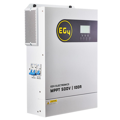
Using technology from the EG4 3kW All-in-One Solar Inverter, the EG4 MPPT100-48HV is a simple, affordable, yet reliable solar charge controller MPPT(Maximum Power Point Tracking).

The EG4 MPPT100-48HV solar charge controller extracts the maximum available power from your PV modules and safely converts it to a lower voltage to charge your battery bank. Optimize your new or existing solar power system by adding this unit and take advantage of additional solar harvesting capabilities.


Powerful PV array MPPT voltage range - No need for combiner boxes
  • Max open-circuit voltage of 500VDC
  • 5500W max usable solar panel PV array power when combining 2 strings with a branch connector
  • 22A max PV string current
100A max charging current for quick battery charging rates - Adjustable from 0A-100A(Default 80A).
  • Capable of charging a 5.12kWh EG4 battery in ~1 hour @ 100A
  • Recommended operating usage: 80A total or 30A per battery to maintain battery lifespan
Battery voltage: 48V nominal.
  • 48-62VDC charging voltage (default 56Vdc)
Built-in breakers for added protection.

  • PV array DC disconnect breaker
  • Built-in battery breaker for added protection
Effective and efficient

  • 94% max charge controller efficiency
  • Less than 25W self-consumption
BMS Communication
  • The MPPT charger is able to communicate with EG4 batteries when operating with non-EG4 compatible inverters via its RS485 BMS port.
What is an MPPT Charge Controller?

An MPPT, or maximum power point tracker is a DC-to-DC converter that optimizes the power between the solar panel array, and the battery bank. Basically, they convert a higher voltage DC output from solar panels down to the lower and consistent voltage needed to charge batteries.
""""""

The Above is stated based on their EG4 3000 inverter with 500VDC MPPT Let's look at that Advertising:

""""""

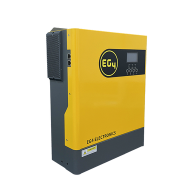
EG4 3kW Off-Grid Inverter | 3000EHV-48 | 3000W Output | 5000W PV Input | 500 VOC Input​

3000EHV-48's Design Improvements:

  1. Larger Battery Terminal Connections(Supports up to 2 AWG)
  2. Minor Improvements to the exterior design
  3. Fully compatible with V1 units(may require a simple firmware update, can be found on www.eg4electronics.com)

The EG4 3000EHV-48 is a 3000W all-in-one, multi-function inverter/charger; it combines the capabilities of an inverter, MPPT solar charger, and battery charger to offer uninterrupted power support in a single, portable-sized package. Its comprehensive LCD display offers user-configurable and easy-accessible button operation including battery charging current, AC/solar charger priority, and acceptable input voltage based on different applications.

This compact powerhouse is perfect for small barn builds and small critical loads panels as it easily supports lights, an average fridge/freeze, or a 9K BTU Mini Split.

BONUS KIT INCLUDED ($149 value)

  1. Wifi Stick with Remote Settings Adjustment
  2. 125A UL listed Nader Breaker and Din Bracket
  3. 6Ft 4 AWG Red and Black Battery Cables

Features:

Built for Off-Grid

Performance Components

  • Lightweight
  • Smaller Footprint Than Other Comparable Models
  • Overload Protection
  • Overtemperature Protection
  • Short Circuit Protection
  • User Customization via LCD Display

Reliability & Safety Testing

  • 3-Year Warranty Supported and serviced out of Texas
"""""""'"

Notice anything missing from the first page specs...something that should be listed as it is important?

Had to dig for it but the current with 500vdc on EG4 3000 inverter is 18a max . So it is lower.

IMG_6427.jpeg
IMG_6425.jpeg


Mppt are dc to dc conversion. With step up - step down transformers when you step up voltage to get higher volts less amps. When you step down voltage amps tries to rise. They obviously can’t feed 500vdc into the batteries. I’ve never seen a print on these mppt…. Anybody got one?

The mppt you have is the EG4 3000 MINUS THE 3000 INVERTER section..

OP earlier post
“‘’’If I was running parallel strings where the amps would double, then I would be concerned with wire heating resulting in power loss. At 12.67A at peak sun, it is not a concern with running 10AWG in a single string.”’’’’
‘’’Vmp of my panels 41.84V. Imp is 12.67A. 8S comes to Vmp of 335V.“
~4241 watts

According to their specs you are GOLDEN. You got 2 EG4 mppt ~ $800.00 FOR much less then Victron 450/100. ~$1230.00. ~$430 savings goes long ways towards wire. Look at that victron. Think Victron recommend battery 2awg wire….for that one. Victron Recommended Fuse ~ 125 - ~150amp …..cross section is wire concern with dc.


Interesting
IMG_6428.jpeg

IMG_6431.jpeg
Interesting.

…. My PV for 100ft run of red and 100ft run of black was around ~$115 total. Understand you on the conduit ….

Thanks
 
Last edited:
With the EG4 MPPT or the 3K AIO, it really isn't a problem concerning max amperage if the string has a VOC close to max with temp coefficient factored in. I'm running 4.2Kw of panels per string, it fits really well with the EG4 MPPT. I'm running slightly larger mono panels, with bifacial panels it could get close to max input but I have seen as high as 4.7Kw from each string with some cloud edge effect.

I'm not sure on over paneling the MPPT's. I never tried and these work very well for my application. Over paneled with cloud edge effect could be a little risky, I'll let someone else try it.

Interesting on the Victron float voltage setting and the string voltage maximum.
 
Last edited:
  • Like
Reactions: D71
Push it all the way through and trim if needed.

I suppose it depends on who you ask, but when I started using ferrules the guideline was to have the wire sticking out of the ferrule a small amount.

My reference for this was a White Paper by Weidmuller in PDF format. I don't recall where I found it but I have a local copy. This web page on their site says the same thing. See the "Do's and Don'ts" section.

 
@Zwy Glad Signature Solar is taking good care of you. Really nice of you to keep us updated, very helpful video!
 
Back
Top