Not to mention the cost savings in copper if you'd had to run more....Looking back on power generation today, we hit a 121.5 amps @ 48v, incoming from the 4 arrays
That converts to 243 amps @ 24v,
yet the highest current flow before the voltage change, was 221 amps @ 24v, which is a gain of 530 watts of more power
Definitely a great gain by switching to the higher voltage, and avoiding the charge controller OVER CURRENT limits
You are using an out of date browser. It may not display this or other websites correctly.
You should upgrade or use an alternative browser.
You should upgrade or use an alternative browser.
Solar house generator I started DIY back in 2000 - My path from Trace to Xantrex (on FLA battery) to XW Pro inverters on Tesla Model S batteries
- Thread starter dougbert
- Start date
dougbert
Solar Addict
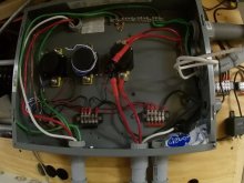
The incoming PV contactor panel box is an old service panel I modified to house the 4 relays/contactors, one for each of the incoming arrays
here are 3 of the final 4 contactors in the midst of being installed
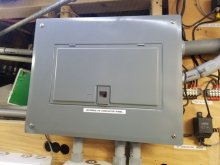
I finally found the old cover for this box and mounted it
The contactors get warm by being energized while the panels are producing
so I installed a small 40mm PC fan on the bottom
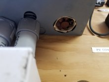
to push some air in from the bottom and it flows out at the top and other various holes
The fan only runs when the contactors are engaged
I might install a second fan on the other end. Some air flow is better than none
Making use of re-purposed equipment, which many of my parts are
here are 3 of the final 4 contactors in the midst of being installed

I finally found the old cover for this box and mounted it
The contactors get warm by being energized while the panels are producing

so I installed a small 40mm PC fan on the bottom

to push some air in from the bottom and it flows out at the top and other various holes
The fan only runs when the contactors are engaged
I might install a second fan on the other end. Some air flow is better than none
Making use of re-purposed equipment, which many of my parts are
dougbert
Solar Addict
It is the best time of day for my system to generate power
12:30pm, 30F outside and mostly cloudy. As I was monitoring it got brighter outside as the clouds parted and full clear sun shone down.
I looked at the monitoring meter and I watched as the power level was at 6k, then 6.1, 6.2, 6.4, 6.6, 6.7. 6.8, 7.0 and hovered at 7.1kw for about 15 seconds then declined as clouds moved in.
7100 watts - I was bowled over
I went through my arrays and totaled the "rated" power output listed and the summary was
6820 watts
If I had not glanced over I would have missed it and there is no log to record it
amazing
dougbert
Solar Addict
through the Conext Gateway web page, I was watching the "Power Flow" meter which does not have logging. It does log under the "Battery Summary"Wowza... but my Schneider 60 150 had logging, do you mean combined total, you need the Schneider battery monitor...
dougbert
Solar Addict
Today's power plot log
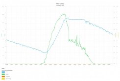
BULK charge until noon when target voltage attained.
ABSORPTION at 12:45 or so and flat voltage
H2O heater diversion engaged around 12:30 PM and ran until 4:30PM, output 1000watts @120vac
This evening I swapped out the 240v 4500watt coils (@120v they output the 1000w)
and installed the new 120v 2000w coils (UPPER and LOWER).
So the next time the system/batteries are full, it will put 2000watts into the water heater.
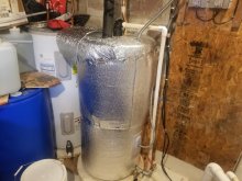
Going to heavily insulate the tank.
During BULK, the panels output 6000watts
then during ABSORPTION (the flat voltage line @49.8v) and the 1000w water heater turned on, the panels output 3000watts
With the 2000w water heater coils installed now, I expect the panels to output 4000watts
and that still leaves 2000watts un-utilized power of the panels
What to use it for?
1) In the summer, the attic fan and the window AC unit will be running
2) might add a 2nd AC unit
3) Still trying to teach my wife to run the diskwasher, vacuum, washer and dryer and such at that "battery full" state but.....
4) Add more battery capacity
Last edited:
dougbert
Solar Addict
I explained most of this in a prior post sometime ago, but will do it again here
I heat my water with a NatGas tankless heater and I love it. Never run out of hot water. It has a feature that it will accept warmed incoming water and by so doing will reduce the consumption of NatGas to finalize the heating of the water.
What I have are 2 50 gallon Electric water heater. Currently just one tank is plumbed upstream from the tankless, but it has been wired with the 240v 4500watt coils. Run at 120vac, each coil produces 1000w. But as pointed out in the above post, 2000w of output will be generated.
My goals is to plumb a 2nd water heater upstream of the current one and implement the diversion load to heat water in the following sequence:
1) downstream tank UPPER
2) downstream tank LOWER
3) upstream tank UPPER
4) upstream tank LOWER
each of the UPPER and LOWER coils have a pass on thermostat that stop heating once target temperature is reached.
As shipped from the factory, the UPPER thermostats have a Normally Open tap that connects to the LOWER thermostat. When the UPPER reaches target temperature, it turns off the UPPER coil and enables the LOWER coil.
By replacing the LOWER thermostat with a new UPPER thermostat, a pass through can also occur and allow the upstream tank UPPER coil to become enabled
See http://waterheatertimer.org/How-to-wire-water-heater-thermostats.html for more info
Section: Non-simultaneous thermostats control 2 water heaters
In this picture are 2 of the downstream tank's coils and one of the upstream tank's coil
I need to order a 4th 2000w coil to finish the upstream tank's lower coild
Also is the downstream tank's lower thermostat. I installed an UPPER thermostat there
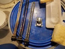
Here is the downstream tank's upper thermostat
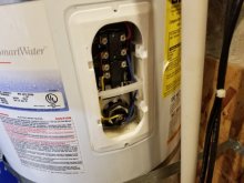
Here is the downstream tank's lower 'new' pass through thermostat. Two of the tap screws is where I will add 2 wires and extend out to the upstream tank's input wires. I will put a hole in the cover and use some armor covered wire to run to the upstream tank
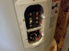
And here is the upstream tank in the back
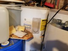
I heat my water with a NatGas tankless heater and I love it. Never run out of hot water. It has a feature that it will accept warmed incoming water and by so doing will reduce the consumption of NatGas to finalize the heating of the water.
What I have are 2 50 gallon Electric water heater. Currently just one tank is plumbed upstream from the tankless, but it has been wired with the 240v 4500watt coils. Run at 120vac, each coil produces 1000w. But as pointed out in the above post, 2000w of output will be generated.
My goals is to plumb a 2nd water heater upstream of the current one and implement the diversion load to heat water in the following sequence:
1) downstream tank UPPER
2) downstream tank LOWER
3) upstream tank UPPER
4) upstream tank LOWER
each of the UPPER and LOWER coils have a pass on thermostat that stop heating once target temperature is reached.
As shipped from the factory, the UPPER thermostats have a Normally Open tap that connects to the LOWER thermostat. When the UPPER reaches target temperature, it turns off the UPPER coil and enables the LOWER coil.
By replacing the LOWER thermostat with a new UPPER thermostat, a pass through can also occur and allow the upstream tank UPPER coil to become enabled
See http://waterheatertimer.org/How-to-wire-water-heater-thermostats.html for more info
Section: Non-simultaneous thermostats control 2 water heaters
In this picture are 2 of the downstream tank's coils and one of the upstream tank's coil
I need to order a 4th 2000w coil to finish the upstream tank's lower coild
Also is the downstream tank's lower thermostat. I installed an UPPER thermostat there

Here is the downstream tank's upper thermostat

Here is the downstream tank's lower 'new' pass through thermostat. Two of the tap screws is where I will add 2 wires and extend out to the upstream tank's input wires. I will put a hole in the cover and use some armor covered wire to run to the upstream tank

And here is the upstream tank in the back

Hedges
I See Electromagnetic Fields!
- Joined
- Mar 28, 2020
- Messages
- 21,011
On a cloudy day with less PV production, would enabling water heater cause discharge of batteries? Would they cycle in and out of absorption phase?
With multiple elements of different wattages, might be possible to enable different combinations in order to adjust consumption.
With multiple elements of different wattages, might be possible to enable different combinations in order to adjust consumption.
dougbert
Solar Addict
On a cloudy day with less PV production, would enabling water heater cause discharge of batteries? Would they cycle in and out of absorption phase?
With multiple elements of different wattages, might be possible to enable different combinations in order to adjust consumption.
Great question
First some numbers
The voltage numbers are from the array charge controllers perspective:
I BULK charge to 50.1v - the tesla battery is FULL at 50.4v - and there is a voltage delta between the charge controllers and the battery bank of .4 volts so the tesla is really at 49.7v - measured by the ESP32 Battery Controller
ABSORPTION is set to 49.8v - that is the flat line on the above log chart
FLOAT is also set to 49.8v
H2O diversion load kicks in at 49.4v after a 5 minute stablization time period
the diversion load turns off at 49.2v after a 3 minute wait time
Once in FLOAT it stays in float until a full charge cycle is started
At the moment, with medium cloud cover, the panels are producing 3.2kw and the battery is approaching 49.5 and the diversion load is now ON
Upon watching it, the diversion load can draw from the battery for about 3 minutes before turning off so the draw down is small.
I have attempted to set things to do the diversion when the batteries are nearly full and it seems to be working well so far
Cloudy today and snow coming tomorrow. Sunshine coming back on Sunday
Had not pondered the more fine tuning route yet, but thanks for the possible option
Last edited:
I'm definitely watching this thread, I want to do water heat as a diversion as well.... it's great seeing you go before me and my Tesla plans.... keep up the great work Guinea Pig, I mean Doug.Great question
First some numbers
The voltage numbers are from the array charge controllers perspective:
I BULK charge to 50.1v - the tesla battery is FULL at 50.4v - and there is a voltage delta between the charge controllers and the battery bank of .4 volts so the tesla is really at 49.7v - measured by the ESP32 Battery Controller
ABSORPTION is set to 49.8v - that is the flat line on the above log chart
FLOAT is also set to 49.8v
H2O diversion load kicks in at 49.4v after a 5 minute stablization time period
the diversion load turns off at 49.2v after a 3 minute wait time
Once in FLOAT it stays in float until a full charge cycle is started
At the moment, with medium cloud cover, the panels are producing 3.2kw and the battery is approaching 49.5 and the diversion load is now ON
Upon watching it, the diversion load can draw from the battery for about 3 minutes before turning off so the draw down is small.
I have attempted to set things to do the diversion when the batteries are nearly full and it seems to be working well so far
Cloudy today and snow coming tomorrow. Sunshine coming back on Sunday
Had not pondered the more fine tuning route yet, but thanks for the possible option
73
Jen
dougbert
Solar Addict
thank you for a great compliment. I document my "builds if things" for 2 purposes:I'm definitely watching this thread, I want to do water heat as a diversion as well.... it's great seeing you go before me and my Tesla plans.... keep up the great work Guinea Pig, I mean Doug.
73
Jen
1) My persistent memory of why, what and how I did things
2) To share AND gather information
I have found the more I share, the more feedback I get and I gain new points of views of options and choices on the subject matter
I expect to make mistakes but I aim to reduce the cost of those mistakes by seeing what others have done and also by actually putting my money where my opinion is in order to PROVE or DISPROVE my opinions.
Today I had great sun (it is waning right now) and produce water of 110F. I don't know how much I produce, but today is wash day and my wife used some warm water heated by the sun as well as run the machines by sunlight.
During the most productive part of the day, my array produced 6kw of power. When the battery was full, and the diversion load was on, the panels produced 4.6kw of power WITH some 1.4kw of power not being utilized.
2kw to the diversion load
500w to the battery
2.1kw to the house and stuff
I think I will connect a 1kw electric heater tomorrow (more sun coming) and test things around that as well
Well I for one am very grateful for the knowledge you are sharing, and wish there was a little tip jar here so those of us who do value it, can toss a couple bucks your way to help you build....thank you for a great compliment. I document my "builds if things" for 2 purposes:
1) My persistent memory of why, what and how I did things
2) To share AND gather information
I have found the more I share, the more feedback I get and I gain new points of views of options and choices on the subject matter
I expect to make mistakes but I aim to reduce the cost of those mistakes by seeing what others have done and also by actually putting my money where my opinion is in order to PROVE or DISPROVE my opinions.
Today I had great sun (it is waning right now) and produce water of 110F. I don't know how much I produce, but today is wash day and my wife used some warm water heated by the sun as well as run the machines by sunlight.
During the most productive part of the day, my array produced 6kw of power. When the battery was full, and the diversion load was on, the panels produced 4.6kw of power WITH some 1.4kw of power not being utilized.
2kw to the diversion load
500w to the battery
2.1kw to the house and stuff
I think I will connect a 1kw electric heater tomorrow (more sun coming) and test things around that as well
73
Jen
dougbert
Solar Addict
I have a couple of days of experience now with the water heater diversion system.
Yesterday I installed a new GFCI 20amp breaker to feed the heater, since all the electrical stuff is right next to the sump pump and other watery things. $48 for that breaker, but if it keeps me (or someone else) alive, it is priceless
Here is the various stages I note on the charging system:
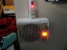
The PV production increases 800 watts when the above heater is on (from 3.8kw to 4.6kw)
Turn it off, PV production falls to 3.8kw
And that, is what the expected behavior should be.
I have that heater behind my chair (my office is in the basement and cool) blowing in to the desk foot hold and I say: It is nice and toasty there. I think I will use this heater during excess power generation times for my personal benefit.
Comment on the "lost" energy that I am currently not using:
With NetMetering, that energy would be "pushed" into the grid battery for later credits.
Yet I don't want to do NetMetering and even if I did want to, I CANNOT. This section of the city is served by a utility circuit that is currently max'ed out. This same circuit connects the big 12megawatt hydro plant to our city system and transmission line is full, awaiting another circuit to be installed.
Jordanelle dam hydroelectric plant: https://wwclyde.net/project/jordanelle-dam-hydroelectric-plant/
The dam is 5 miles north of me.
Therefore, at the moment, I have power to spare on sunny days which I produce myself
dougbert
Yesterday I installed a new GFCI 20amp breaker to feed the heater, since all the electrical stuff is right next to the sump pump and other watery things. $48 for that breaker, but if it keeps me (or someone else) alive, it is priceless
Here is the various stages I note on the charging system:
- PV panels are producing 6kw of power regularly in full sun
- House takes its share of around 1.2kw
- Battery is receiving some 4.8kw during BULK
- Battery reaches 99.4% full and diversion load comes on
- Battery receives .25kw of power
- PV panels are reporting 3.8kw
- assuming water heater is taking 2kw
- house is consuming the rest of 1.4kw
- leaving a PV power of 2.2kw which is UN-UTILIZED

The PV production increases 800 watts when the above heater is on (from 3.8kw to 4.6kw)
Turn it off, PV production falls to 3.8kw
And that, is what the expected behavior should be.
I have that heater behind my chair (my office is in the basement and cool) blowing in to the desk foot hold and I say: It is nice and toasty there. I think I will use this heater during excess power generation times for my personal benefit.
Comment on the "lost" energy that I am currently not using:
With NetMetering, that energy would be "pushed" into the grid battery for later credits.
Yet I don't want to do NetMetering and even if I did want to, I CANNOT. This section of the city is served by a utility circuit that is currently max'ed out. This same circuit connects the big 12megawatt hydro plant to our city system and transmission line is full, awaiting another circuit to be installed.
Jordanelle dam hydroelectric plant: https://wwclyde.net/project/jordanelle-dam-hydroelectric-plant/
The dam is 5 miles north of me.
Therefore, at the moment, I have power to spare on sunny days which I produce myself
dougbert
Last edited:
Hedges
I See Electromagnetic Fields!
- Joined
- Mar 28, 2020
- Messages
- 21,011
While on grid (let them deal with horrible power factor) a heavy-duty light dimmer could be PID-controlled to feed a resistive heating element and keep export hovering around zero. (alternative to stair-step load with and hysteresis time delay)
Or in your case, you're regulating battery voltage not power export?
Or in your case, you're regulating battery voltage not power export?
dougbert
Solar Addict
I have watched a 4 cycle hysteresis pattern as the sun sets in the diversion load for sure. ON/OFF repeated until the battery is not charged enough to continue.While on grid (let them deal with horrible power factor) a heavy-duty light dimmer could be PID-controlled to feed a resistive heating element and keep export hovering around zero. (alternative to stair-step load with and hysteresis time delay)
Or in your case, you're regulating battery voltage not power export?
I assume you are referring to a CAN based PID, right? My inverter is 2005 and does not have that bus. It has a Xantrex proprietary serial link to a PC based program (I can't find one and no info on the protocol). The Tesla battery controller does have a CAN port, and am on a learning curve to play with that in the future but has nothing related to an inverter control, just the battery and an external battery charger with a CAN port.
and yes, just battery voltage operation.
my hope is to learn these embedded busses so I can development my own monitors.
I program devices for PCIE PC cards and the like, not so much embedded stuff - yet
Hedges
I See Electromagnetic Fields!
- Joined
- Mar 28, 2020
- Messages
- 21,011
I assume you are referring to a CAN based PID, right?
and yes, just battery voltage operation.
No, I avoid software and data link implementations for the most part. I like to make fun of how much more expensive and time consuming is to build and install software as compared to hardware.
What I mean is just hook up an analog circuit to measure battery voltage and adjust a light dimmer. PID can be implemented with op amps, resistors and capacitors, or with a digitally programmable module. It could tap in to the electrical portion of a dimmer switch, or could servo the mechanical dial, for fire the triac with your own circuit.
The servo for an RC toy could rotate a dimmer shaft, for instance. (but if constantly moving would wear out the potentiometer so should be slow responding.)
My preferred implementation would be a switcher that takes in AC and simulates a variable resistance, so it draws a sine wave current and drives resistive load with variable voltage sine wave. That requires building power electronics, which is why I suggest triac based light dimmer instead, cheap and light weight.
dougbert
Solar Addict
Ok, I took "PID" to be the entity device on a CAN bus, hence my questionNo, I avoid software and data link implementations for the most part. I like to make fun of how much more expensive and time consuming is to build and install software as compared to hardware.
What I mean is just hook up an analog circuit to measure battery voltage and adjust a light dimmer. PID can be implemented with op amps, resistors and capacitors, or with a digitally programmable module. It could tap in to the electrical portion of a dimmer switch, or could servo the mechanical dial, for fire the triac with your own circuit.
The servo for an RC toy could rotate a dimmer shaft, for instance. (but if constantly moving would wear out the potentiometer so should be slow responding.)
My preferred implementation would be a switcher that takes in AC and simulates a variable resistance, so it draws a sine wave current and drives resistive load with variable voltage sine wave. That requires building power electronics, which is why I suggest triac based light dimmer instead, cheap and light weight.
So I do not know what PID you are referring to or what it means.
My back ground is in computer operating system and device drivers. I know enough hardware to blow some fuses
Hedges
I See Electromagnetic Fields!
- Joined
- Mar 28, 2020
- Messages
- 21,011
"PID" is Proportional", "Integral", "Derivative", three terms of a servo control loop which can be tuned to rapidly zero an error and stabilize with minimal oscillation. Sometimes you can get by with fewer and achieve good enough response. Cruise control of a car can be implemented this way, as an example.
If you could get battery voltage into something like Arduino or Raspberry and output an analog signal to control an SCR light dimmer, you could ramp heating up or down to keep voltage near target. Or communicate with something like an X-10 dimmer.
If you could get battery voltage into something like Arduino or Raspberry and output an analog signal to control an SCR light dimmer, you could ramp heating up or down to keep voltage near target. Or communicate with something like an X-10 dimmer.
dougbert
Solar Addict
just went to check on the water heater diversion and found that it was NOT working!
All status lights were lit, indicating it was running, yet it was turned off - no voltage on the coil!
Doh!
Then it hit me, test the output leads on the lower coil and it was off and the bypass lead was ON!
This means that this tank was completely heated to target temperature and the next tank could be energized.
In 3 hours (1PM to 4PM), using 2000 watt 120v coils
Nice
Last edited:
dougbert
Solar Addict
Similar threads
- Replies
- 4
- Views
- 385
- Replies
- 9
- Views
- 515
- Replies
- 6
- Views
- 523
- Replies
- 11
- Views
- 773


