diy solar

diy solar

96v boat upgrade

I noticed also that the replacement inboard electric motors for boats are all high voltage. That link showed the 20kw motor at 72v
There must be a way to safely run a high voltage battery bank for boats.
 
Here is an old thread along the same lines :


And a place in Florida that does high voltage batteries for boat propulsion up to 144v !


I see you have FL registration on the boat so they may even be close to you.

If you do loop I’d like to buy you a drink when you pass through Lake Erie. ?
 
Last edited:
I'd be looking at what companies like silent yachts are doing


Several other companies doing it now as well

 
It's an interesting thing, I was well into building a restrained 55 ft powercat and got to the lockup shell stage with 3 litre diesel engines, shafts and rudders in then it put me in hospital.
After that scare I put her on hold and we stepped sidways into what we have now and have been out here for 5 years.

With the advances being made now I have toyed with the idea of going back and removeing those engines and going electric.
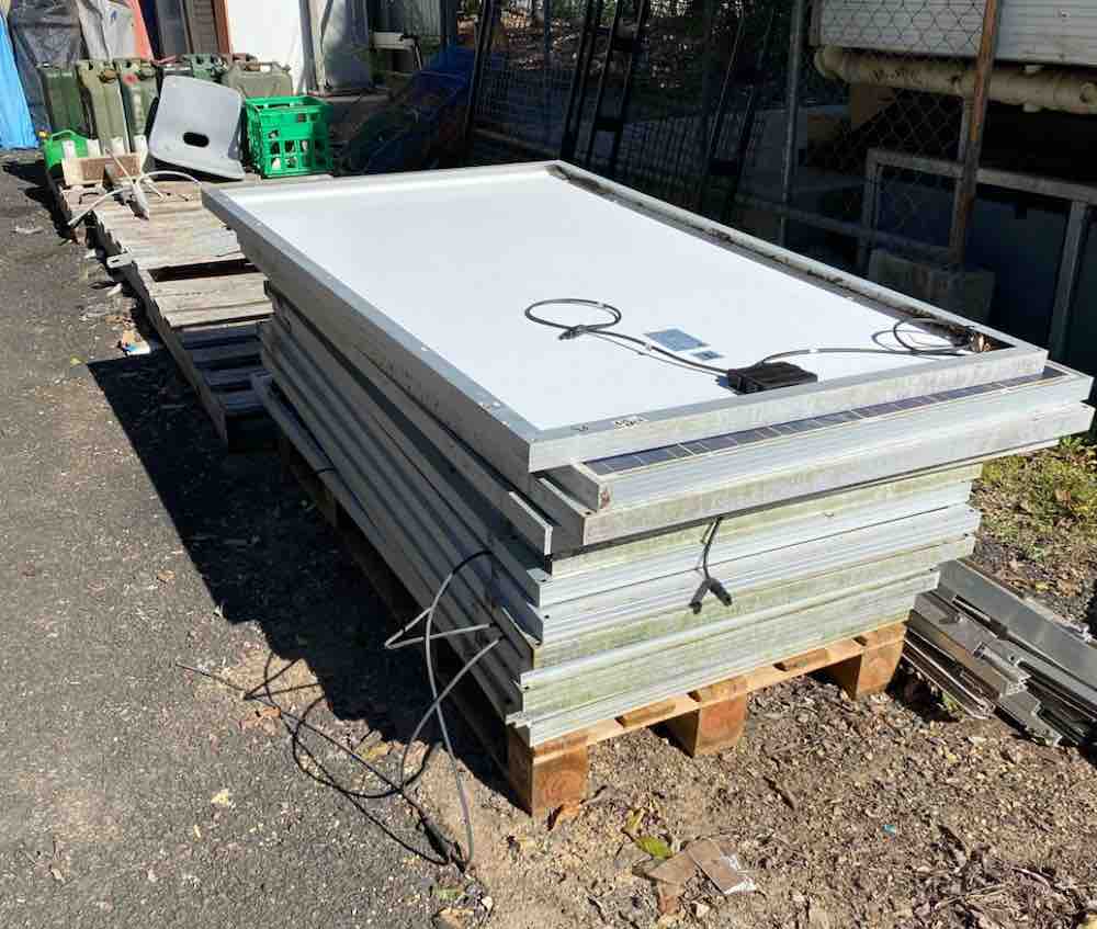
Solar panels can be had for free or near enough

, batteries have come down in price considerably, build a framework seven feet off the deck and cover the entire 55ft X 24ft space with solar.
Shading will keep the boat cool inside as well.

Our cruising style is travel a day and sit for a week at anchor so I could see it working.
 
Last edited:
I went with the REC Alpha panels. Not cheap but they had good power density. 96v system was hard to source out locally so everything else is pretty much coming from China. Already they lost my inverter and had to resend a new one, haha. Hope I get it all.
 
My idea for 96V (haven't ever built one) is dual 48V systems wired in series, middle grounded.
So long as you only grab one wire not both, you get a 48V shock not 96V.

Most equipment would be 48V, readily available.
Have to make sure BMS disconnect can tolerate the voltage (just like two 12V each with own BMS has to tolerate that if you connect in series for 24V). If BMS controls a suitable relay, that should do it.

The two 48V packs would have their own charge controllers and PV panels. If you have 48V loads, try to split between the packs. 96V propulsion motor would use the two in series.
 
Last edited:
My idea for 96V (haven't ever built one) is dual 48V systems wired in series, middle grounded.
So long as you only grab one wire not both, you get a 48V shock not 96V.

Most equipment would be 48V, readily available.
Have to make sure BMS disconnect can tolerate the voltage (just like two 12V each with on BMS has to tolerate that if you connect in series for 24V). If BMS controls a suitable relay, that should do it.

The two 48V packs would have their own charge controllers and PV panels. If you have 48V loads, try to split between the packs. 96V propulsion motor would use the two in series.
Interesting idea. Only thing I don't follow is how you would ground the middle?. Connecting two batteries in series you get one positive and one negative at that middle "ground" point. So at the end of the day you will have one 48v bank with a positive ground and the other 48v bank with a negative ground. unless I am missing something this wouldn't work like you think. I believe it would actually be more dangerous. If you touch either end of the 48v systems to ground you would get a short. If I am missing something let me know.

I think the greater than 48v fear overall is just a fear. Yes its high voltage. Yes it's dangerous. You just need to take the proper safety precautions. I've read lots of diy EV projects over the years and the traction packs they put together are generally 100 volts at a minimum. Some I've see up to 300volts. The biggest problem we had is none of those projects use inverters or solar charge controllers. Which is why our selection was so limited.

I haven't decided yet how we will document the build. I may make YouTube videos for it or just make a build log on this site with pictures as we go. We are eager to see how well it performs. Hoping our theory's on actual power needed to move the boat a reasonable speed are correct!.
 
the problem is totally tractable ?

solar motive applications like this inspire me

hehe get it, tract…..
 
Of course on a boat "ground" may be ambiguous.
And what potentials are present relative to environment can cause corrosion.

Two batteries in series doubles the voltage. If I connected two 48V forklift batteries in series I'd have 96V.
If I used two, 48V chargers to charge each 48V battery separately, that would probably work. If anything in their design referenced ground, elevating that ground to 48V +/- might be a problem.
If I grounded the midpoint, having one charger delivering -48V relative to ground might be an issue. At the very least, I would put its fuse on the negative rather than the positive.

Yes, both +48V and -48V will require fuses (same as both legs of my household 120/240VAC wiring.)

My idea is that two 48V solar charge controllers, which are readily available, would charge the two 48V battery banks.
Propulsion motor control would be fed +/-48V for 96V. So long as its circuit is isolated from ground, should be fine. But if it wired any controls or communication to battery negative that would be a problem. I would expect it to use a DC-DC switcher to supply control circuit. If that's an isolated switcher should be fine, but if common negative that is a problem. All depends on the control circuitry.
 
*taking notes but barely understanding the implication of positive and negative ground*
 
*taking notes but barely understanding the implication of positive and negative ground*

One terminal electroplates, the other corrodes.
Cars used to be positive ground. I think negative ground reduced corrosion issues.
Sacrificial anodes or electrical bias for marine propellers and land-based structures like bridges.

For high voltage breakdown, electron vs. ion, which differ in mass so velocity, affecting impact ionization (single ion causes cascading breakdown in gas.)
Also electron emission from sharp corners, which have enhanced electric field.
 
Of course on a boat "ground" may be ambiguous.
And what potentials are present relative to environment can cause corrosion.

Two batteries in series doubles the voltage. If I connected two 48V forklift batteries in series I'd have 96V.
If I used two, 48V chargers to charge each 48V battery separately, that would probably work. If anything in their design referenced ground, elevating that ground to 48V +/- might be a problem.
If I grounded the midpoint, having one charger delivering -48V relative to ground might be an issue. At the very least, I would put its fuse on the negative rather than the positive.

Yes, both +48V and -48V will require fuses (same as both legs of my household 120/240VAC wiring.)

My idea is that two 48V solar charge controllers, which are readily available, would charge the two 48V battery banks.
Propulsion motor control would be fed +/-48V for 96V. So long as its circuit is isolated from ground, should be fine. But if it wired any controls or communication to battery negative that would be a problem. I would expect it to use a DC-DC switcher to supply control circuit. If that's an isolated switcher should be fine, but if common negative that is a problem. All depends on the control circuitry.
I agree a boat "ground" as you say is not really the same as in a car. Especially since it is all fiberglass. I still can't really see the benefit from a safety perspective of splitting the 96v pack, you still end up with 96v on the boat either way. However I do like the idea from a component perspective. It solves by far the biggest issue we had, finding a decent 96v charge controller and inverter. At this point in the project we finally did find them, although all are coming from china, with not many reviews.. So unintentionally much of the project will end up being product reviews as well. haha.. I guess if they don't work out we can still split up the pack. We already planed on doing that with the Overkill BMS since the highest voltage they go to is 48v, and we didn't like the looks of the "other" 96v BMS options.

When you say grounding the midpoint, do you mean actually connecting that point to the "grounding" points on all of the equipment, as in "earth ground" I am guessing Not? but just wanted to clarify. With a high voltage system like this you wouldn't want the equipment grounding point to be the same as the "Negative battery" point. With two 48v battery packs, I would treat the midpoint as just a simple wire connecting the two 48v systems together, nothing more. I wouldn't "ground" it to anything. As far as the charge controllers being wired in series like that, seems to me like they wouldn't know the difference, but I have never experimented with that.

I also believe, (not positive) most charge controllers outputs are isolated from the case grounding points. so you could ground the equipment together and then to whatever other metal structures on the boat you wanted.

Have you thought about what happens to the 2 48v packs during discharge, while using the 96v system. Since they are separate one could end up at a lower SOC than the other? I suppose you can solely rely on the BMS to take care of that?
 
Two 48V packs would diverge in SoC, especially if you put an inverter on one. Two separate charge controllers would make each full.
two 48V BMS wouldn't balance between the packs, just within.

REC makes BMS that can be branched to several for hundreds of volts.
 
Finished and tested boat. 96v 28kwh lifepo4 battery. Everything went very well except the motor. It is a 12kw hub motor and when I used over 3kw it would overheat. China is not making good on it. So have to look for another motor. Any suggestions?
You can watch some of my test runs here.
 
Back
Top