diy solar

diy solar

EG4 6000 EX blew Up

You would totally fail an inspection by an electrician, town, or insurance agent. Get a certified electrician to redo your cabling to meet local code, which will also most likely fix your problem.
I took off all my cable management to test the equipment. I have already passed local and home insurance inspections. Although, once I figure this out I'll likely redo all the AC wires with 6/3 wire in conduit.
 
I ran out of heat shrink and wire. Initially I only had one inverter. I bought red battery cable and used it for both positive and negative to the inverter. I then got a second inverter and cut the battery cables shorter to reach both inverters.


The battery connections to the inverters are via a negative and positive busbar. I added 150 amp breakers between each inverter's positive connection between the inverters and busbar, and a 200amp breaker between the battery positive and the positive busbar.
View attachment 156570+View attachment 156571

I did some research on paralleling inverters and made sure both AC L1 output to the same leg on the sub panel when I was connecting them and vise versa with the L2 output. I'll have to get some red tape to make it easier to see in the future. but I retraced each wire and verified that they are on the same leg in the sub panel. View attachment 156572

I also made sure to match the AC inputs as well. Although maybe its a case of me overthinking it. I have wired 3 other systems are are working fine but this is my first time doing parallel. I wish I had went with the 6500. Please see my picture below that shows my multimeter can read negative voltage.

View attachment 156573
Thanks for following up and the detailed explanation. It never hurts to check things again. Everything looks good, though it's tough to follow all the red wires in the photos.
Good luck getting it resolved.
 
The breaker for the slave input is the size of one space. Good chance it i only on one side of the panel.
The red wire of the mini breaker goes to the left side of the panel. Does the red wire of the full size breaker go to the left side of the panel? Test to see if you have 240 between red of mini and red of full size? This would be a problem. If you have checked to make sure the reds are on the same side of the panel then disregard.
 
The red wire of the mini breaker goes to the left side of the panel. Does the red wire of the full size breaker go to the left side of the panel? Test to see if you have 240 between red of mini and red of full size? This would be a problem. If you have checked to make sure the reds are on the same side of the panel then disregard.

That's a good idea. I tested them individually and I tested between black and red and got 240v. But, I did not test between red and red. However, I am unable to do that now because L2 AC output does not work anymore.

Edit:
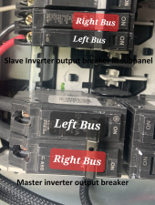
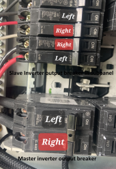
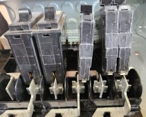
No need for the test. I can visually see that was my problem. The wires are in the same position however, the way the sub panel is designed. regular breaker and mini breakers are inversed. The top position of the mini breaker lands on the right side of the sub panel, and the top position of the regular breaker lands on the left side of the subpanel.
 
Last edited:
That's a good idea. I tested them individually and I tested between black and red and got 240v. But, I did not test between red and red. However, I am unable to do that now because L2 AC output does not work anymore.

Edit:
No need for the test. I can visually see that was my problem. The wires are in the same position however, the way the sub panel is designed. regular breaker and mini breakers are inversed. The top position of the mini breaker lands on the right side of the sub panel, and the top position of the regular breaker lands on the left side of the subpanel.
Yeah, that's what I meant by L1 and L2 being crossed. I'd say test with a meter to be absolutely certain after you get it all ready to fire up again. I'm probably overly paranoid about that kind of stuff but I tested mine at the main panel then tested again at inverters, even though visually I could see they were right. I've been known to think I was seeing something right only to find out I was seeing what I expected to see, not what it actually was. Glad you figured it out! An expensive and time consuming lesson.
 
Figured I'd share, since I have one of these panels and clarify the Right and Left when you have adjacent mini 240v breakers.
1688918956925.png

20230709_165348.jpg
 
The good news is that now the lines are not mixed-up and I tested it with a multimeter. However, the first inverter still does not provide power to AC output line 2. It does not give an error code. I'm thinking maybe a fuse was blown in the first inverter. the unit did come with an extra fuse. However, I don't know if replacing it would void the warranty since its in the top half of the unit. Anyone have any experience with this?

I have not turned on the subpanel breakers yet because its not operating correctly yet.
I’m not so sure you still have a warranty some of the main suppliers follow the site, at this point I would just replace the fuse and hope for the best it’s now obvious it was a wiring problem not a equipment issue
 
I have now Idea why my system blew up. I have two EG4 6000ex split phase inverters I am trying to parallel. I had been running on one inverter for a few weeks. after receiving the second one I connected it via the manual and it made a loud pop and displayed error code 09. I contacted technical support and they found no error in my setup and provided me a replacement. I verified that both inverters were connected per the manual, confirmed both inverters were on the the software and I bypassed the neutral bonding which I did not do the first time because I'm grounded at the service panel and it still blew up as soon as I turned it on. However, second inverter blow the mosfets and the 1st inverter lost one of the AC output legs.

Help please. I don't know why it does not work. Please see below picture of my setup. the off-grid inverts are the eg4 6000ex inverters. the one on the left is the one that blew the mosfets and the one on the right lost one of the AC output legs. Each inverter has its own output and input breakers. The Grid-Tie inverter is its own separate system that only connects to the main panel. Both inverters had the same settings with setting 28 set to Parallel, and I even watched the signature solar videos and turned the inverters on in the same order they did on the video.

View attachment 156526
what happened What solution did you find or error of setup idk any??!!
please would be glad to talk 5635177061 or post photos here DIY forum
 
Back
Top