diy solar

diy solar

EG4 18kPV Q+A general thread

Have you read the manual? 18kpv can be installed before or after the main.
parts of it. Yes I read your last comment saying it could be installed after. As I said that makes sense then that the grid input could still be used as an output to cover the main panels loads..
 
Have you read the manual? 18kpv can be installed before or after the main.
But with the 200amp pass thru I would assume the main application of this inverter is to passthru a possible 200amps of grid power which would mean that it should be installed between the meter and the main panel.
 
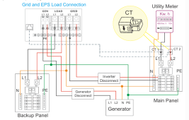
if your diagram like this BACK UP & MAIN PANEL without the generator.
The inverter will always provide power to inverter (EPS) load side as long you have battery power when the grid it out.
The grid will support the load if the inverter reach ON-GRID CUT OFF.
if you have a any load on the Main Panel and you install the CT like in the diagram, the inverter is bidirectional so it can back feed power through the grid input of the inverter and it will try to zero out using the CT reading.


diag.png
 
But with the 200amp pass thru I would assume the main application of this inverter is to passthru a possible 200amps of grid power which would mean that it should be installed between the meter and the main panel.
keep in mind that most HF Inverter will not be able to start with any high surge tools or appliances.
 
BTW: Let's talk a little about 'zero export'.

There is no such thing as true zero export for a hybrid inverter.... particularly for a split-phase inverter. The inverter can get dang close to zero export, but no hybrid out there can claim there will never be a single electron exported. The circuitry to do that would be big and expensive. Unless the user is hyper-sensitive to it, the hybrid inverters will get close enough to zero that it really makes no difference.

Unfortunately, some Utilities have digital meters that will catch that brief transient backload. Some utilities are reasonable and don't complain about the few watt-hours that might show up over a month. As long as the inverter is UL listed for safety, it should not matter to them. Unfortunately, some utilities take a ridiculous zero-tolerance approach and complain about the first back-fed electron.
That is exactly what is going on, and not only with the LP/EG4 inverter. L1 could be drawing 1000 watt from the grid, while L2 could be pushing 1000 watt to the grid. The meter would technically read "0" but the smart meter would see it as back feeding on L2 if the utility wants to make a point.

Marketing wise, I think they shouldn't call it "zero export". That sets too much of a expectation.
They should label it "near zero export" or something.
 
But with the 200amp pass thru I would assume the main application of this inverter is to passthru a possible 200amps of grid power which would mean that it should be installed between the meter and the main panel.
Think of the high pass-through as expanding the possible applications of the inverter, not as limiting it to a particular application.

Some folks will opt to split the loads and wire the inverter after the main panel. That gives them the assurance that critical loads are the only thing powered in an outage, but they have to decide at install time what will and won't be backed up and can't easily change their mind during an outage.

Other folks will opt to only have the main panel. In my house, trying to split the loads would be a minor nightmare, so I would opt to just put the inverter between the meter and the panel. That means I can run anything during a power outage, but maybe not everything at the same time. When I look at my usage history, it very rarely spikes above 12kw and when it does it is very brief. With the 18Kpv's run surge spec, there is a good chance the battery capacity will be the limit during a power outage, not the inverter wattage. In fact, If don't use my oven and AC at the same time, I am 99% sure the load would remain under the 12KW.

Both approaches are valid and the inverter is intended to support both approaches.

BTW: In the manual, they have examples of both types of configurations.
 
Last edited:
12kw Inverter Fan start and stop logic.
START : Total power higher than 6kW or max.
START : Inner temperature higher than 75 degrees Celsius
STOP: Total power lower than 4.8kW and max.
STOP: Inner temperature lower than 65 degrees Celsius.
Would it be possible for LuxPower to give a more aggressive fan option? My units are also >110degreesF ambient environment and if the internal temperatures are being allowed to get up to 75degreesC, I am concerned about long term life of the electrolytic capacitors. I wouldn't mind if the fans went full on at >50degreesC internal. But my units are out in the shop and noise isn't a factor for me. So an option which allowed more aggressive fan usage seems like a good mix for all. Or maybe an installer option for complete adjustment of all of the above mentioned parameters with maximums still being enforced.
 
That is exactly what is going on, and not only with the LP/EG4 inverter. L1 could be drawing 1000 watt from the grid, while L2 could be pushing 1000 watt to the grid. The meter would technically read "0" but the smart meter would see it as back feeding on L2 if the utility wants to make a point.

Marketing wise, I think they shouldn't call it "zero export". That sets too much of a expectation.
They should label it "near zero export" or something.
I tend to look at it like we are simply supplied 240v from the electric company. thats how the meter that most people have figures out their power usage. They don’t keep track of our home usage using 120v.. this means the standard smart meter will not see backfeeding on one leg.
Example; if one leg of the home is using 20amps at 120v and no load on the other leg, the meter only sees that as 10amps at 240v.
There is a few inverters that supply splitphase 120-120 gridbtie output instead of single phase 240v. Then there wouldn’t be any over supply on one leg
 
with the inverter installed after the main panel. if I had a critical loads panel with just the essentials on it and a main panel with all the rest of the homes loads on it. And I had the inverter grid input supplying inverter grid tie power to the main panel, the critical panel would also be fed by a breaker in the main panel, therefore the grid input is also supplying the critical panel. So then what happens when the grid goes down and the inverter begins to supply offgrid power to the critical panel. with the critcal panel wired to the main panel via breaker the main panel would be fed offgrid power possibly frying a lineman..
Or when the grids available the inverter can supply grid tie power to cover the main panel and at the exact same time cover the critical panels needs via the inverters AC output. therefore not needing a wired connection between the critcal offgrid panel and the main panel for the critical loads to be powered when the grids up.
I guess the breaker and connection from the critical panel to the main panel isn’t needed. I suppose the inverter would supply the critical panel (thru the inverters AC output) and at the same time supply only enough power to the main panel (via the inverters AC input) until the main panel loads are satisfied, therefore doing zero export.
 
I tend to look at it like we are simply supplied 240v from the electric company. thats how the meter that most people have figures out their power usage. They don’t keep track of our home usage using 120v.. this means the standard smart meter will not see backfeeding on one leg.
Example; if one leg of the home is using 20amps at 120v and no load on the other leg, the meter only sees that as 10amps at 240v.
There is a few inverters that supply splitphase 120-120 gridbtie output instead of single phase 240v. Then there wouldn’t be any over supply on one leg
I looked further into this, and it looks like you are correct in some cases:

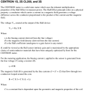
I looked up technical manual of my Itron Smart meter CL200

Screenshot from 2023-08-07 08-36-26.png
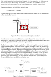
Screenshot from 2023-08-07 08-36-50.png
both currents are added up in the hall-effect sensors and the total current times 240 volt(ish) volt is calculated and is referenced as the power.

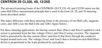
The next meter model up has 2 separate hall effect sensors, one for each phase:

Screenshot from 2023-08-07 08-41-09.png
Screenshot from 2023-08-07 08-41-23.png
So (like a lot of things in life) it depends on what meter you have if they can actually measure L1 & L2 individually.

Today I learned...
 
Last edited:
I guess the breaker and connection from the critical panel to the main panel isn’t needed.
I am not sure what breaker that would be. However, someone might implement a transfer switch that allows the selection of the Inverter AC out or a direct connection to the main panel. This would be to isolate the inverter for service and would be wired such that the critical load panel could never get power from both the inverter and the main panel.
 
I have asked if the fans can be individually controlled and suggested some fan logic options.
I would be happy for a fan or 2 to run gently to keep it around 100-110 under light/no load.

Could you not just get a couple of 120mm hi output CPU fans ($15.00) and mount them below the unit to blow across it ??
 
I looked further into this, and it looks like you are correct in some cases:

I looked up technical manual of my Itron Smart meter CL200

View attachment 161513
View attachment 161514
both currents are added up in the hall-effect sensors and the total current times 240 volt(ish) volt is calculated and is referenced as the power.

The next meter model up has 2 separate hall effect sensors, one for each phase:

View attachment 161515
View attachment 161516
So (like a lot of things in life) it depends on what meter you have if they can actually measure L1 & L2 individually.

Today I learned...
I researched this heavily before I started using zero export inverters.. Short answer is that almost all meters people have on their homes only see our power usage as 240v. They only have one Ct in the meter that BOTH legs go thru. For the math the meters ALWAYS divides the amps the Ct sees in half. So if the home is only using a 240v 20amp load, the CT sees that as a 240v 40amp load because both legs go through one Ct. The meter simply divides that by .5 to get the actual 20amps at 240v being used by the home.. if the home is only using a 20amp 120v load on one leg then the meter still divides those amps by .5 which makes the meter see that load as a 240v 10amp load which is the same power as a 120v 20amp load..
if there’s a combination of 120v and 240v loads being used the total amps the single Ct sees is still divided by .5 and then a 240v reference used..
 
Last edited:
I am not sure what breaker that would be. However, someone might implement a transfer switch that allows the selection of the Inverter AC out or a direct connection to the main panel. This would be to isolate the inverter for service and would be wired such that the critical load panel could never get power from both the inverter and the main panel.
if I installed one of these inverters after the main panel I would want an interlock breaker (or transfer switch) used for the Ac output and grid connection to the critical loads panel. As you said for maintenance. I would have it so the grid (bidirectional inverter AC input) always covered the loads in the critical panel unless there was a power outage then the interlock breaker or tranfer switch would allow the critical panel to be supplied by the inverters AC output..
 
I'm about halfway through this thread (I just found it), but I posted about my potential build in the 'safety check section' when I might have been better served here.

Can someone check this "week one plan" for me as I'm very early in the planning/research phases, and I need to give my solar/battery savvy friend a rest from questions.

 
I got my 18kpv today, took out the manual and started reading. I thought I had this figured out but now I’m even more confused. I am focusing first on the hardware setup.
I currently have 2 6500s and 6 livepower4 batteries.
The way I figured the wiring was suppose to go is, take the grid line in wires from my 200a panel, connect those to the inverter line in. Then from the line out of the inverter to the 200a panel where the grid lines were. Then of course connect the cts, batteries and pv.
After looking at the manual, it is showing to use service taps to the inverter. It also shows a transfer switch, which I thought this inverter had one in it.
My plan is to export to the grid and also use the grid for backup and assistance when needed.
Can anybody clear this up for me?
Some jurisdictions might require a transfer switch to bypass the inverter incase of equipment failure.
 
Back
Top