diy solar

diy solar

DIY 48v 280ah Build - Blowout/Fail

Don't compress your cells. They are going to last so long on a solar system they will age out before they fail by expansion. I don't understand why people still do this.

As other stated the failure is likely short circuit between the cells. You need non-conductive dividers between the cells, don't just rely on the plastic.

Why would two separate battery packs have nearly identical failures?

If the condition is overvoltage, why didn't his BMS trip?
 
I dis-assembled my Banks/Cells last night. In my un-wiring and thinking through my setup, looks like I mistakenly had/have a Negative battery lead parallel to the BMS B- / P-, through each Battery Breaker. Thus bypassing the ability of the BMS to disconnect the cells upon over charging.
This was late last night. So still more later. But I think its making more sense now that the problem is "Me". I messed this up on both Banks.
More to follow.
I appreciate all the constructive comments and help. With my work schedule, It will be a few days to prove the above true.
 
Do JK BMSs have a shutdown switch to test proper install? My Overkills have a switch where you can manually shutoff a battery bank.
 
Yes, you can do that through the app (both charge and discharge independently).

I'm not talking about software. I'm talking about having a physical port on the BMS that allows a mechanical switch to turn it on/off.

Overkill has both software/app control like you mentioned and a physical switch port. I can walk down to my setup and flip all my batteries off without a disconnect. (I have a disconnect anyway for redundancy)
 
I completed my DIY build(s) a few days ago. 32 Cells total, 16S, 280ah EVE Cells, JK BMS(s) B2A24S20P, Growatt 5000ES units, Solar Assistant.
All electronics appear working as designed.
My 1st 16S battery build running the past month, maybe past 30-40 days. Clean, no observed issues. JK Active balancing normal. My 2nd 16S battery build put together and online this past Friday.
All looked clean, running normal.
I walked out to the Shop (external garage) and Growatt fans noise running normally. All indications looked fine from a 6-7 ft distance. As I get closer I can smell this funky smell. Strange smell, liquid on the lower battery cells. Vented cells I believe.
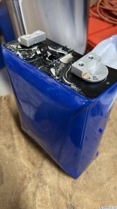
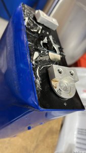
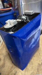
Both battery banks appear as blownout/swollen/fail cells #9/#10.
Weird thing, all electronics (Growatts & JK BMS) running and reporting normal. JK units actively balancing. Growatts actively charging. No fire, but massive heat around Cells #9/#10. Those cells swollen, Cell #9 lower/Bank2 vented. No breakers tripped (Nader 125Amp) on either bank. No actual explosion.
I immediately shutdown system.
Still Assessing damage. Possibly wait until they cool down. Waiting to disconnect and evaluate.
Very lucky no fire.

Damn, damn, damn. Expensive fail.
Need to assess and decide what I did wrong. Obvisously something.

BANK-1 Upper & BANK-2 Lower (Before Event)
View attachment 170284
BANK-1 (1st Build) Before Event
View attachment 170280
BANK-1 After Event (Swelling Cell#9)
View attachment 170281
BANK-2 Lower (AFTER Event) Cell #9/#10/#11
View attachment 170285

Constructive comments appreciated, anything obvious noted?
I dont see any non conductive material seperating each cell. You cannot rely on that thin blue plastic. The shelf is wood, so non conductive. The straps also have metal contacting the cells.
Check BMS paramaters to make SURE they are correct. Otherwise, it looks like a short or faulty cells.
 
I dont see any non conductive material seperating each cell. You cannot rely on that thin blue plastic. The shelf is wood, so non conductive. The straps also have metal contacting the cells.
Check BMS paramaters to make SURE they are correct. Otherwise, it looks like a short or faulty cells.
It comes down to "Mis-Wired" BMS - Battery leads. And then overcharging and BMS unable to stop charging.

Here's a photo of the blownout cell from Lower Bank. Cell #9

IMG_2227.jpg
IMG_2228.jpg
IMG_2229.jpg
 
It does not use pwm, but combines the output of four low frequency square wave inverters.
Each of these inverters has an output transformer that has a different secondary voltage. The four secondaries are connected in series to directly generate an analog ac sine wave. Its rather like direct digital to analog conversion at hundreds of volts and thousands of watts.
Each square wave inverter has potentially three output states +ve, zero, and -ve. There are four inverters (four bits).

As you will know, four bits of binary can only produce 2 x 2 x 2 x 2 = 16 output voltage levels.
Four bits of "trinary" can produce 3 x 3 x 3 x 3 = 81 output voltage levels.
That is an 81 step peak to peak sine wave, forty steps up, zero, and forty steps down.

I developed this gradually myself over many years. The original prototypes all used various microcontrollers to generate the required switching waveforms. But I gradually simplified it down to be an all hardware design (no software crashes !)
This makes it a lot easier to understand and repair for people that are not software geniuses.

At least two other software guys have come up with firmware that duplicates my hardware design using a Nano microcontroller.
There are now three different Warpverter driver boards available to do all of this from three different people. All are 100% compatible with identical plugs and identical functionality. Its all free and completely open source if you wish to build one yourself.

No data screens or firmware. Its a basic bare bones inverter, dc in, ac out. No problem adding a second microcontroller for purely monitoring, alarms, logging or control. That would be quite independent of the basic inverter function, so you can add whatever you want yourself.

As a retired professional power electronics design engineer, its been a bit of a part time hobby. Having designed mass produced commercial inverters and uninterruptible power supplies, overcoming the technical problems is what I do.

The only problem with it is its not commercially viable, its too expensive to build compared to pwm. So its only value is as a home project where you wind your own transformers and use recycled parts.
The biggest advantage is all the switching is done at at a very low frequency, so the circuit layout is far less critical than high frequency pwm, where it becomes increasingly difficult to successfully parallel multiple devices for very high power.

This is what the secondary voltages look like. All waveforms shown with the same oscilloscope settings.
Impressive.

Probably more than I can do based on my knowledge.
 
Always good to learn from others’ mistakes for sure. Fortunately this one was all My Fault. No arcs or sparks, no fires. Nobody hurt.
My system will be better off because of me learning.
Now to find (4) additional 280ah cells.
It almost happened to me.
When I first started out I hooked up the BMS and all the wires. Connected a charger to the battery.

Notice I said battery not BMS. Fortunately, I was monitoring the BMS although it wasn’t controlling anything it was still reporting voltages.

Once cell was @ 3.7 when I looked and that led me to the “oh shit” moment and I disconnected the charger.

Happens to all of us at one time or another.

Yup, I did the same thing early in my build process.
 
With all respect to those who have far more experience than I, I am not a fan of "tight clamping".

My understanding is that cells expand when being charged. This is a physical manifestation of a chemical event. This expansion "could" be contained if the entire cell casing was constructed like a "pressure cooker", or similar device. A tight strap around the cells will only cause the inevitable swelling to occur in another path of least resistance. But it WILL occur. The "bus bars" are pretty much rigid, unless built of flexible material. They will maintain the distance between the terminals while the cell expands. This could put great force on the terminals.

I'll be happy to be shown to be wrong. But it's not easy to break the laws of chemistry and physics without unwanted consequences.
Those cells are not compressed adequately. Compressed cells are held between solid compression plates using threaded rod to evenly apply the end plate pressure. I am never seen 'compression" so poorly done. It looks like a disaster waiting to happen
 
Back
Top