diy solar

diy solar

24V batteries in parallel - what type of fuse?

JWLV

-.-. --.-
Joined
May 27, 2020
Messages
579
I'm in the process of putting together four 24V 200A LiFePo4 batteries in parallel.
I have some questions about fuses.

See this diagram.
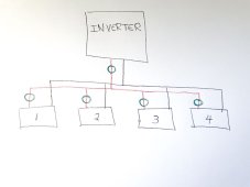
diagram.jpg
The batteries are labeled 1-4. The green circles are where the fuses will go. I know that a fuse is needed at each battery. What about a fuse at the inverter? Or will a circuit breaker switch be adviseable there? Or both?

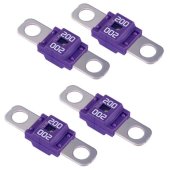
The inverter is 3000W. So I am planning to use 200A fuses, like this one on Amazon: https://www.amazon.com/Current-Trucks-Construction-Vehicles-Caravans/dp/B0BZVR7V5W
fuse.jpg
Is this the right type of fuse? Is 200A the proper size for this system?

I prefer bolt-down fuses so that I won't have to get more cables.
 
Class T fuses would be proper. Amperage depends on system voltage and max load capacity, usually an inverter.
 
The issue is the massive current your LiFePo4 can push if there is a short

From memory I think it's 20x their rated amps, youve got 800amp, x20 = 16,000amp short circuit current

Those midi fuses have a max 'interruption rating' of 1,000 amps . So if something goes wrong they are NOT going to protect your system

 
Last edited:
I'm working on this same issue. When Will put his EG4 bank together, I just see a single 200a Class T fuse on the positive line to the inverter.

Do we really need fuses on each individual battery pack (whether it be a single server rack or a series pack)?
 
Do we really need fuses on each individual battery pack (whether it be a single server rack or a series pack)?
I don’t know where the source data for this answer is, but because of the huge amounts of current, I went with a class t for each battery and after combined.
 
Because there is a huge amount of current that can go through these batteries in parallel, wouldn't I want to have a fuse that will blow at a much lower amperage? In my example, I have four 200A 24V batteries. So I think a 200A fuse at each battery would be the correct size. That means if any one of the batteries is drawing more than 1C (or 200A), that battery's fuse will blow and the rest will continue on. At the inverter, the maximum amperage will be 800A, but a fuse might not even be necessary there since each battery will already have been limited at 200A each. The idea is to catch anything that might go wrong and stop any one of the batteries from drawing more than 200A.

Does this make sense to anyone or am I completely wrong on this?
During normal situations, sure, you would be protected by the BMS… but fuses are for ABNORMAL failure protection.
Electronics like BMS devices fail… and having one short closed, and dumping all the power the cells can will cause massive problems… properly sized fuses that can handle the AIC current of the build is wise.
 
Because there is a huge amount of current that can go through these batteries in parallel, wouldn't I want to have a fuse that will blow at a much lower amperage? In my example, I have four 200A 24V batteries. So I think a 200A fuse at each battery would be the correct size. That means if any one of the batteries is drawing more than 1C (or 200A), that battery's fuse will blow and the rest will continue on. At the inverter, the maximum amperage will be 800A, but a fuse might not even be necessary there since each battery will already have been limited at 200A each. The idea is to catch anything that might go wrong and stop any one of the batteries from drawing more than 200A.

Does this make sense to anyone or am I completely wrong on this?
Now after the four 200 amp fuses are combined, they can deliver 800 amps down the next connector.

In that case I fuse the feed to the inverter at the highest amperage that would be delivered to the inverter.

In my 2p battery build I decided on 125 amps per battery and 200 amps conbibed.
 
The issue is the massive current your LiFePo4 can push if there is a short

From memory I think it's 20x their rated amps, youve got 800amp, x20 = 16,000amp short circuit current

Those midi fuses have a max 'interruption rating' of 1,000 amps . So if something goes wrong they are NOT going to protect your system


I don't quite understand what you are saying. If something horribly goes wrong and 16,000 amps goes through, a 200A fuse would blow up so fast it would be like lightning struck it. And if it does have a max interrupt rating of 1,000 amps as you say, what difference does it make? The fuse is made to blow if anything above that current goes through it. Do you mean that the 200A fuse will not work if more than 1000A goes through it? What is expected to happen on a 200A fuse if, say 5000A goes through it?

I don't want a fuse to keep the system working when high current ( >200A ) goes through it. I want a fuse that'll blow and stop and shut down the system when high current goes through it.


What I *think* will happen in that case you're talking about, 100amp mega fuse with 5,000amps passing over it, is the fuse will weld / ark closed and will not interrupt the current as expected .

BUT I'm sure others more knowledgeable than myself will pitch in with a proper explanation


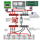
Below is a standard diagram for setting up Parallel Batteries.
- Each Pack is fused per its Rating, also accounting for surge capacity. See your BMS Specs.
- Battery Bank disconnection is important for maintenance, repair or other. There are switches available that will work with 48V (60 Volt) battery systems... The BlueSea switch shown in diagram is perfectly fine for 24V.
- for a 24V System, you can safely use MRBF Fuses which work perfectly and are cost effective too.
- EACH device has either a Breaker or Fuse as shown. If you chose to use Breakers, then use only Quality DC Breakers ONLY ! Note that DIN-Rail Breakers are easier to work with as you have more options for mounting in either a box or on a locked rail. * Most Codes now require Polarized Breakers (long overdue).

MRBF: https://www.bluesea.com/products/5191/MRBF_Terminal_Fuse_Block_-_30_to_300A
Class-T & Mega Fuses: https://www.bluesea.com/products/category/15/Fuses
Breakers can be had from BlueSea or Midnite Solar (warning: There are bad knockoffs out there, avoid at all costs, stick to known good as suggested)
Switches: https://www.bluesea.com/products/category/11/Manual_Battery_Switches


gram Parallel System-setup PNG.png
 
This diagram is awesome thank you!

I have some of those BlueSea switches rated for 48v, is that ok on a battery where the voltage may go up to 50v+?
 
This diagram is awesome thank you!

I have some of those BlueSea switches rated for 48v, is that ok on a battery where the voltage may go up to 50v+?
When we use the term 48V it is for legacy equivalences. 16 cells @ 3.650V = 58.4V so we round out to a max of 60V.
The switches are designed to handle up to XX Amps & XX Volts.

LFP has 2 Voltage Ranges (like all other chemistries).
The Allowable Range which is from 2.500-3.650 volts per cell. This is the voltage range that causes No Harm or Damage to the cells. Above or below that range will cause harm.
The Working Range is from 3.000-3.400. This is where the Rated AH of the cells comes from. This is also the Testing Range for compliance by manufacturers. In the ESS (Energy Storage Systems) the most common profile is to charge up to 3.450Volts per cell which allows for post-charge settling (all LFP settles post-charge) with a Low Volt cutoff around 2.800 Volts per cell. The cutoff is ABOVE the LVD to prevent the BMS from bricking itself if any single cell voltage is too low.

There are people who insist on pushing the cells to the edges which is of no benefit or gain but more often than not causes odd issues of High & Low Volt disconnects or out of balance states.
 
I have 24v system and am using MRBF terminal fuses on each battery, mainly because Class T was hard to find when I set up my batteries. I like them because mounting right onto the battery makes for a compact install.
I would use class T if I had a 48 volt system.
 
Do server rack batteries with built in breakers need to be individually fused as well?
 
I have some of those BlueSea switches rated for 48v, is that ok on a battery where the voltage may go up to 50v+?
I don’t know, but to me 48 volts is maximum so I among other reasons when I upgraded from 12 volts, I chose to go to 24 volts because I would see a max of 32 or 33 volts.

There’s “24 volt” fuses that are rated to 33 volts which will handle an equalization, but this switch is rated to 48 volts.
 
Would it be safe to use this fuses for two battery banks in parallel 280Ah 1P16S and 187Ah 1P16S
Model of fuse is RGS12 CR2L 250/500V below in attachment is some datasheet.
And should i put mccb circuit braker bwtween hybrid inverter and battery banks or just battery switch?
 

Attachments

  • CATALOGUE RGS12 175A.pdf
    785.3 KB · Views: 3
Back
Top