diy solar

diy solar

3000W Inverter/charger connection to BMS/Battery question

Starry-Nights

New Member
Joined
Nov 4, 2019
Messages
23
I have a eight 100 amp 3.2V LiFeP04 cells connected as a 100 amp 24V battery with a Daly 8S 24V 200amp BMS. I also have a 3000W / 9000W surge Inverter Charger. The BMS has 6 AWG cables which seem nowhere near the required 1/0 AWG minimum for the inverter. I at first thought of connecting the inverter directly to the battery, and not through the BMS first, but that would seem it could make the BMS completely bypassed. I have looked at some other BMS's but the cables on them seem pretty wimpy too. Suggestions, simple wiring diagram greatly appreciated!

One additional related question: I am using a Epever 30Amp MPPT and live in NH where the temps have starting dropping into the 20's at night. The controller has a Temp sensor, but I can find no setting to stop charging when temp goes below freezing. The Daly BMS does not seem to have this capability either. To handle, I have installed a simple thermostat the cuts the solar array off at 34 degrees and resumes and 37. It has a 20 amp relay and it works great for the solar (four 100W panels, configured as 24V), but would not work for the higher amps of the inverter/charger. Additionally, I have a 12V to 24V Sterling Battery to Battery unit I have yet to install that can supply up to 70 amps.
 
You need to buy the victron battery protect and either set it to cut off at the low voltage itself, or run a relay from the bms as detailed here: https://www.mobile-solarpower.com/design-your-own-12v-lifepo4-system.html

Low temperature is more tricky. The epever triron has this ability, not too sure about the others. As for the b2b charger, just connect to a cable that turns live on ignition, and run it through a switch. Leave the switch on in the summer, but in the winter turn it off and manually turn it on once the cabin has warmed up from freezing, you might be able to wire this cable into your thermostat relay too. The only other way around this is to wire your thermostat to a heat mat and then this can run independent of anything else as the batteries never get frozen. The inverter load is irrelevant as discharging below freezing isn't a problem.
 
You need to buy the victron battery protect and either set it to cut off at the low voltage itself, or run a relay from the bms as detailed here: https://www.mobile-solarpower.com/design-your-own-12v-lifepo4-system.html

It's very worth noting that the referenced schematic shows a Victron BatteryProtect connected in a way that it should never be connected; that is, directly between a battery and an inverter. This is not a supported connection and absolutely will irreparably damage the BatteryProtect the first time you turn on the inverter (whether under load or not). As the tech support manager of an authorized Victron distributor -and the guy who runs the test bench here- please, take it from me to completely disregard the referenced schematic. Victron BatteryProtects ARE NOT designed to do what's being shown in the diagram.
If you're looking for a bistable voltage-programmable relay that can handle the massive inrush current of an inverter (and could therefore handle being placed in the position of the BatteryProtect shown in the schematic), the Sterling ProLatch-R is your best bet. It's designed to do this, and there's not a significant cost difference between the two.
There may well be other options as well, but we are extremely selective in the brands that we distribute, so the Sterling is the only device we trust for this application. And don't get me wrong, I love the Victron BatteryProtect line, but it's not designed for this type of usage, and although Victron has so far been really great about honoring all the warranty claims caused by people hooking them up this way, there's only so long I would expect their patience to last.

tl;dr: do not ever use a BatteryProtect as the referenced schematic shows.
 
That's interesting, not heard that before.

4. The short circuit protection of the BP will be activated if you try to directly connect loads with capacitors on their input (eg inverters). For that use case, please use the BP to control the remote on/off switch on the inverter, instead of disconnecting the higher power DC line


So get the 65A victron bp, connect all 12v loads to this, connect inverter directly to battery, use bms with relay to trigger both bp and inverter remote on undervoltage/overvoltage situation. That's a pretty perfect solution right there and it's cheaper and lets you run massive loads.

These relays were always the achilles heel I was trying to solve, it never occurred to me to use the inverter remote disconnect.
 
Last edited:
That's interesting, not heard that before.

4. The short circuit protection of the BP will be activated if you try to directly connect loads with capacitors on their input (eg inverters). For that use case, please use the BP to control the remote on/off switch on the inverter, instead of disconnecting the higher power DC line

So with that in mind if you might be able to use a relay off the bms to disconnect the inverter's remote switch and not bother with a battery protect at all, or at worse, get the cheapest version for 12v loads.

Yes, although they never supported the connection (because the BP is designed to be used in Victron systems, and Victron inverters have programmable low-voltage disconnects already, so they literally never considered them being used this way), they have recently updated the device manuals to reflect this. In the referenced schematic, of course, the BP is shown disconnecting the high-amp DC line, and that fries the BP... the worst part is that it often welds the FETs closed, which means they never disconnect, but you wouldn't know that until it was too late and your battery was dead.
Can confirm that you can use the BP to control a remote on/off, but as you say... you don't need one of these, then, you just need a cheap little relay.
I'm still a fan of them for regular DC loads - I use three of the Smart BP 65A models in my truck for Bluetooth switching/low-voltage shutdown of my various exterior lighting- but I'm honestly just tired of processing BP and Smart BP warranty claims from them being hooked up to inverters or inverter/chargers, so I've started kind of crusading across the interwebs trying to stop them being used this way.
 
Which manual? Can you post a link?

At the time, battery protects were being used on professional installs with inverters. I have never fried one either. Can you post a video of one that you destroyed?

Also, if its just the inrush, just short out the terminals on the battery protect, then turn it on. I will post a update to my page so that people can short out the termianls real quick, and boom, you can still use a battery protect. Not a big problem at all.
 
Even better, you can short the bp terminals with a resistor. For larger inverters. Super easy solution

And I can find it on the manual: https://www.victronenergy.com/uploa...rt-Battery-Protect-65-A--100-A--220-A-EN-.pdf
Where is it?

Wow the Sterling ProLatch-R is awesome.

What about using a normal relay? I dont need the low voltage disconnect. I just need a big switch. I dont care if its a battery protect or sterling. And the self consumption of a large relay isnt a big deal. But a HUGE relay that can handle hundreds of amps would be awesome. What do you recommend? @Justin Laureltec

And the 100 amp battery protect can handle 30 seconds of 600 amps. Really hard to believe it cant handle charging some caps. Is it really that weak? Looking forward to your response and manual reference
 
Last edited:
@Will Prowse no... no, never short out the terminals, and never connect directly to an inverter, and please don't post any videos telling people to do this. That's not what these devices are for, and I was literally brought to this forum by customers who were calling me for BatteryProtect warranty replacements because they destroyed their BatteryProtects by following schematics and instructions posted here, including the schematic referenced above. Stop doing this if you value the delicate electronics that you're trusting a potentially expensive (in dollars or in man-hours to put together) battery bank to.

The document that you reference is the datasheet, not the manual; the datasheets haven't been fully updated yet, but all manuals for the BatteryProtects and Smart BatteryProtects have been updated to reflect this: https://www.victronenergy.com/uploa...A-100-A--220-A-EN-NL-FR-DE-SE-SV-PT-TR-IT.pdf
That's just the BatteryProtect version, but you'll find that the Smart BatteryProtect model instruction manual has been updated as well. You will note in the included schematics that the BP is only being used to control a remote on-off switch on the inverter, not disconnecting the main DC line, in accordance with the instruction manual line: 4. The short circuit protection of the BP will be activated if you try to directly connect loads with capacitors on their input (eg inverters). For that use case, please use the BP to control the remote on/off switch on the inverter, instead of disconnecting the higher power DC line.

It should go without saying that one should never, ever try to workaround the short-circuit protection of the device by shorting the BP terminals with a resistor... for obvious reasons, this would defeat the purpose of having a BP inline in the first place.

As for a big switch, yes, the Sterling ProLatch-R has 4 different settings, each with their own fully custom-settable voltage triggers, and models up to a 240A version... and yes, it's just a big, programmable, bistable, magnetically-latching (so very low self-consumption) mechanical relay. Whether or not it's actually suitable for what you need depends entirely on what you're trying to do, but it is far more suited for usage in the above-referenced diagram than a Victron BatteryProtect, because it's actually designed to do what's being shown. All that being said, it's also pretty expensive for just a basic relay... I'm betting that, if you don't need the programmability, you could get a much cheaper relay elsewhere.
 
Last edited:
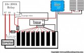
how does this look? Should work great
View attachment 1721
Sure, that'd work perfectly well, and honestly would probably be quite a bit cheaper than buying a Victron anyway. Like I've said before, the BP line has a very important and useful place in a good DIY system if you have the need/money for it, it's just that it's not necessary or appropriate in this particular place.
 
Its done. I will post an update on the video and on the community section of the channel. I have used them for years at a time with inverters, and so have many other professional level installers which I can show you. I did not create the idea to do this on my own, I have been seeing people doing it this way for awhile. But all we need is a switch, so its pointless to use any of these. BMS will manage the on/off of relay and there is no need to have the features of prolatch or battery protect. And yes, much cheaper. Thank you for telling me. Only takes a few seconds to change this on the site and update everyone with a email.
 
If there is ever an update to a product, let me know and I will change/update videos/posts/website pages as needed. Thank you for telling me this
I'll try to keep in touch; honestly I'm not sure if they realized when they released the BP line that people might be using them this way, as they seemed genuinely surprised at the flood of returned units... and it's taken a good 4-5 months to get updated product manuals since the problem was really truly identified, so it's all just something we've been trying to work around. Hopefully someone will come out with a really viable alternative, as Sterling's unit can't be triggered by a BMS and is a royal pain to program, so it's not exactly a replacement either. I guess sometimes keeping it simple is best until the tech catches up to the needs that people are trying to fill!
 
Wow, this has been amazing to watch this thread develop! I really wonder what percentage of users with a BMS and Inverter have them wired correctly! Many thanks to Justin and Will for coming up with a solution and wiring diagram I can follow. I will look forward to the video.

Tom
 
Last edited:
I JUST installed a BP-220 last weekend doing it the wrong way! Time for a rewire. The directions that came with mine didn't show or mention this. The updated manual, linked above, was updated last week! Hot off press. Thanks for sharing!
 
Back
Top