


You are using an out of date browser. It may not display this or other websites correctly.
You should upgrade or use an alternative browser.
You should upgrade or use an alternative browser.
4 X class solar flares to impact this weekend.
- Thread starter JLD
- Start date

Dagoth Ur Does Solar
Solar Enthusiast
I love coming to the forum, because I get my daily dose of "THIS is the big thing that's gonna end humanity in a few days, no really THIS is the one this time, it's something nobody knows about, but trust me bro!"
Plain old news media fear mongering just doesn't do it for me anymore... I need my dose from Internet folks...
Plain old news media fear mongering just doesn't do it for me anymore... I need my dose from Internet folks...
AlaskanNoob
Solar Enthusiast
- Joined
- Feb 20, 2021
- Messages
- 957
I love coming to the forum, because I get my daily dose of "THIS is the big thing that's gonna end humanity in a few days, no really THIS is the one this time, it's something nobody knows about, but trust me bro!"
Plain old news media fear mongering just doesn't do it for me anymore... I need my dose from Internet folks...
Who said this was going to end humanity in a few days? In this thread?

skyking1
Solar Enthusiast
LOL that's nothing. My neighbor went out, he saw something but I said hey my phone made some great pictures. After we look at them a while he reveals he's really colorblind. It was all one tone to him, like wildfire smoke 
Checkthisout
Solar Wizard
- Joined
- Nov 14, 2021
- Messages
- 4,904
LOL that's nothing. My neighbor went out, he saw something but I said hey my phone made some great pictures. After we look at them a while he reveals he's really colorblind. It was all one tone to him, like wildfire smoke
That's what I thought early evening as well. We hiked to the the top of a hill so we could see better. I was wondering why it was dam smokey.
Checkthisout
Solar Wizard
- Joined
- Nov 14, 2021
- Messages
- 4,904
One thing that tripped me out was the flickering/waving action of the light.
It puts into perspective how fast the solar wind is moving across the earth's atmosphere.
It puts into perspective how fast the solar wind is moving across the earth's atmosphere.
AlaskanNoob
Solar Enthusiast
- Joined
- Feb 20, 2021
- Messages
- 957
Transformers have two or more inductor windings, coupled by a core.
At nominal operating voltage and line frequency, a 100A 240V 25kVA transformer might carry a couple amps (2% of rating). The current is 90 degrees later than voltage, so the energy it absorbs one phase is returned to the grid next phase, minus I^2R losses.
With current able to flow in the secondary, magnetic field is canceled and current goes higher, e.g. 100A at full load.
With no load, the core gets turned into a permanent magnet, with poles reversing every phase. That's magnetic domains of atoms reversing each phase (resisting change in field and current flow), and partially "saturating", running low on more domains to reverse. If you double AC voltage or cut frequency in half, it will saturate and current will shoot up to whatever resistance limits it to, about 35x rated current.
If you apply DC voltage to the winding, it resists current briefly. About 10 milliseconds or so at 240V, about 1 second at 2.4V. Then transformer core saturates, it stops resisting AC voltage, and current from AC power supply shoots up 35x, burning out the transformer.
The damage to transformer is cause by power coming from power plant. The DC current from CME, EMP, or a solar panel connected to one winding causes the inductor to stop working, so current is no longer limited. (Transformers can be used as amplifiers this way.)
The utility wouldn't like it if your transformerless inverter failed and PV string backfed DC.
If I'm correct in trying to digest this, it's not so much the DC voltage amount going to the transformer that is the issue, but the fact that any is going to the transformer because it causes the transformer to lose the ability to limit AC power that comes from the source which will burn it out.
In our case, the power plant is our inverter and our inverter's max output is below what the transformer can handle, so that should be a measure of protection for us were a CME to introduce DC voltage on our 650' cable to our transformer, right?
If your panel array is spead over thousand miles it might have some effect.Does this affect off-gridders as well?
safe to say that it doesnt have effect on off-grid installations.
Quattrohead
Solar Wizard
Conditions were no good tonight. I set an alarm but no dice. Apparently they were seen in our part of central Florida last night.
If I'm correct in trying to digest this, it's not so much the DC voltage amount going to the transformer that is the issue, but the fact that any is going to the transformer because it causes the transformer to lose the ability to limit AC power that comes from the source which will burn it out.
It's not the DC current up one and down another of the three lines of the three-phase transmission line that's an issue. The three lines run close together and pick up essentially the same voltage along their length, like a twisted pair (they are actually a twisted threesome, essentially the same idea, with a one-third twist every few towers, to cancel out differences in the induced or capacitively coupled voltages.) The issue is DC (or ultra-low frequency AC) in the "common mode" - induced the same direction in all three wires and returning by a somewhat different path through the grounding.
The lines need a DC path to ground, to prevent the atmosphere's about 100v/meter vertical field from charging up the lines, as they run over hills or higher, to voltages that would arc over and damage equipment. So to a first approximation the typical long-haul transmission line is fed by three transformers in a Y configuration, with the center joint grounded. You have to ground it at both/all ends, so you don't have it "floating" when the breakers are open. So the three wires as a group act like a single long wire (see "phantom circuit") and the connection to the local ground at the ends completes the circuit.
Your main problem is with the long transmission lines that run intercity distances in close to a straight line. When the solar flare bombardment squeezes the earth's magnetic field, causing it to move relative to the transmission line, they pick up as much as about five volts per mile. Since the "squash" is wider than one face of the planet this just keeps adding up, mile after mile. Voltages are also induced in the ground under the wires. But the ground is non-uniform so it doesn't match the voltage of the wire above it and cancel out.
Since the squash lasts minutes to several hours the DC / low-frequency is "on" in a particular direction for a very long time, so the inductance of the transformer doesn't provide any limit to the current, which (in timescales of seconds) is determined just by ohm's law, the induced DC / low-frequency voltage (which becomes substantial over many tens of miles during a magnetic storm), and the line/ground/wire/winding resistance (which are all quite low). So if nothing is done about it you can get a substantial DC / low-frequency current in the windings.
Meanwhile there's a big AC voltage across the transformer from the generated power. The resulting current is limited by the inductance of the coils, and the coils are wound around an iron core, which increases the magnetic field, and thus the inductance (compared to a coil without such a core) by a large factor. But as the current rises the core can only become magnetized up to a point. Once it's fully magnetized (saturated) the inductance boosting effect disappears, and further increases in current only "see" the inductance of the coil as if it didn't have a core. So the current rise from a given increment of voltage is that same "factor of many" larger than when the core isn't saturated.
Transformers are built with enough core material to handle the normal currents from rated capacity operation plus a safety margin for typicl events. But in a geomagnetic storm, on a long transmission line, the magnetization from the current from the common-mode induced voltage adds to the cyclic magnetization from the line's AC. If the total is enough to saturate the core, you get massive spikes of current during some parts of the cycle, and this can quickly damage the transformer and/or the wiring or other equipment.
You can get the same effect on the neighborhood / rural distribution network if the drop transformers are Y connected - but it's not as pronounced, because the distances are shorter and there are ground connections at every "pole-pig" transformer.
But the real problem with the long transmission lines is that the house-sized substation transformers are custom-built, there isn't a big supply of them just waiting to be installed, even once you've got one it takes weeks to set it up, and one or two of 'em being knocked out can take out several small towns or much of a big city. If you fry a whole bunch of them at once, it could take months to years to get power back to much of the service areas.
The solution is to put something in those connections between the Y center and the local ground. A resistor to limit DC / low-frequency induced currents, maybe bypassed with a big capacitor to keep things running smoothly when the phases aren't balanced or one line has a fault, a current detector that fast-trips the disconnect, etc. These are big and pricey. But now that the issue has been identified the utilities have been adding such protection (sometimes voluntarily, sometimes due to government mandates) for years. As with the old Y2K problem, by the time we get a really bad mag storm or carrington event we might just have things fixed up enough that it won't be such a big deal.
If your panel array is spead over thousand miles it might have some effect.
safe to say that it doesnt have effect on off-grid installations.
Also: it won't be a significant issue unless you ground those many miles away panels.
The two wires for each string run close enough together that they
might as well be a twisted pair as far as solar storm frequencies are concerned.
If the miles of wire from your panels to the charge controller are only pathed-to-ground
at the charge controller end, the panel end can "wave up and down" by as many volts
as its insulation can handle with no problems.
Aridom82
Learning addict
I read that a big enough solar storm, as big as the Carrington event or bigger, could damage not only the power lines infrastructure but the electronics as well, computers, phones, our inverters, etc.As with the old Y2K problem, by the time we get a really bad mag storm or carrington event we might just have things fixed up enough that it won't be such a big deal.
Is that true or just baloney? Can solar storms induce dangerous currents in small electric devices?
wpns
Solar Joules are catch and release
Thank you for this, it finally makes sense!It's not the DC current up one and down another of the three lines of the three-phase transmission line that's an issue. The three lines run close together and pick up essentially the same voltage along their length, like a twisted pair (they are actually a twisted threesome, essentially the same idea, with a one-third twist every few towers, to cancel out differences in the induced or capacitively coupled voltages.) The issue is DC (or ultra-low frequency AC) in the "common mode" - induced the same direction in all three wires and returning by a somewhat different path through the grounding.
The lines need a DC path to ground, to prevent the atmosphere's about 100v/meter vertical field from charging up the lines, as they run over hills or higher, to voltages that would arc over and damage equipment. So to a first approximation the typical long-haul transmission line is fed by three transformers in a Y configuration, with the center joint grounded. You have to ground it at both/all ends, so you don't have it "floating" when the breakers are open. So the three wires as a group act like a single long wire (see "phantom circuit") and the connection to the local ground at the ends completes the circuit.
Your main problem is with the long transmission lines that run intercity distances in close to a straight line. When the solar flare bombardment squeezes the earth's magnetic field, causing it to move relative to the transmission line, they pick up as much as about five volts per mile. Since the "squash" is wider than one face of the planet this just keeps adding up, mile after mile. Voltages are also induced in the ground under the wires. But the ground is non-uniform so it doesn't match the voltage of the wire above it and cancel out.
Since the squash lasts minutes to several hours the DC / low-frequency is "on" in a particular direction for a very long time, so the inductance of the transformer doesn't provide any limit to the current, which (in timescales of seconds) is determined just by ohm's law, the induced DC / low-frequency voltage (which becomes substantial over many tens of miles during a magnetic storm), and the line/ground/wire/winding resistance (which are all quite low). So if nothing is done about it you can get a substantial DC / low-frequency current in the windings.
Meanwhile there's a big AC voltage across the transformer from the generated power. The resulting current is limited by the inductance of the coils, and the coils are wound around an iron core, which increases the magnetic field, and thus the inductance (compared to a coil without such a core) by a large factor. But as the current rises the core can only become magnetized up to a point. Once it's fully magnetized (saturated) the inductance boosting effect disappears, and further increases in current only "see" the inductance of the coil as if it didn't have a core. So the current rise from a given increment of voltage is that same "factor of many" larger than when the core isn't saturated.
Transformers are built with enough core material to handle the normal currents from rated capacity operation plus a safety margin for typicl events. But in a geomagnetic storm, on a long transmission line, the magnetization from the current from the common-mode induced voltage adds to the cyclic magnetization from the line's AC. If the total is enough to saturate the core, you get massive spikes of current during some parts of the cycle, and this can quickly damage the transformer and/or the wiring or other equipment.
You can get the same effect on the neighborhood / rural distribution network if the drop transformers are Y connected - but it's not as pronounced, because the distances are shorter and there are ground connections at every "pole-pig" transformer.
But the real problem with the long transmission lines is that the house-sized substation transformers are custom-built, there isn't a big supply of them just waiting to be installed, even once you've got one it takes weeks to set it up, and one or two of 'em being knocked out can take out several small towns or much of a big city. If you fry a whole bunch of them at once, it could take months to years to get power back to much of the service areas.
The solution is to put something in those connections between the Y center and the local ground. A resistor to limit DC / low-frequency induced currents, maybe bypassed with a big capacitor to keep things running smoothly when the phases aren't balanced or one line has a fault, a current detector that fast-trips the disconnect, etc. These are big and pricey. But now that the issue has been identified the utilities have been adding such protection (sometimes voluntarily, sometimes due to government mandates) for years. As with the old Y2K problem, by the time we get a really bad mag storm or carrington event we might just have things fixed up enough that it won't be such a big deal.
wpns
Solar Joules are catch and release
I’m going to say no, though the fiction writers and doomsayers don’t find any interest in that.I read that a big enough solar storm, as big as the Carrington event or bigger, could damage not only the power lines infrastructure but the electronics as well, computers, phones, our inverters, etc.
Is that true or just baloney? Can solar storms induce dangerous currents in small electric devices?
Not that significant grid disruptions wouldn’t put a big dent in so-called “civilization”
Hedges
I See Electromagnetic Fields!
- Joined
- Mar 28, 2020
- Messages
- 21,095
I believe we did not have the technology to detect the Carrington Event at the time and today we still miss about a third of CMEs from what I understand.
Well, it was just lower tech. And that Event is named after the guy who detected it.
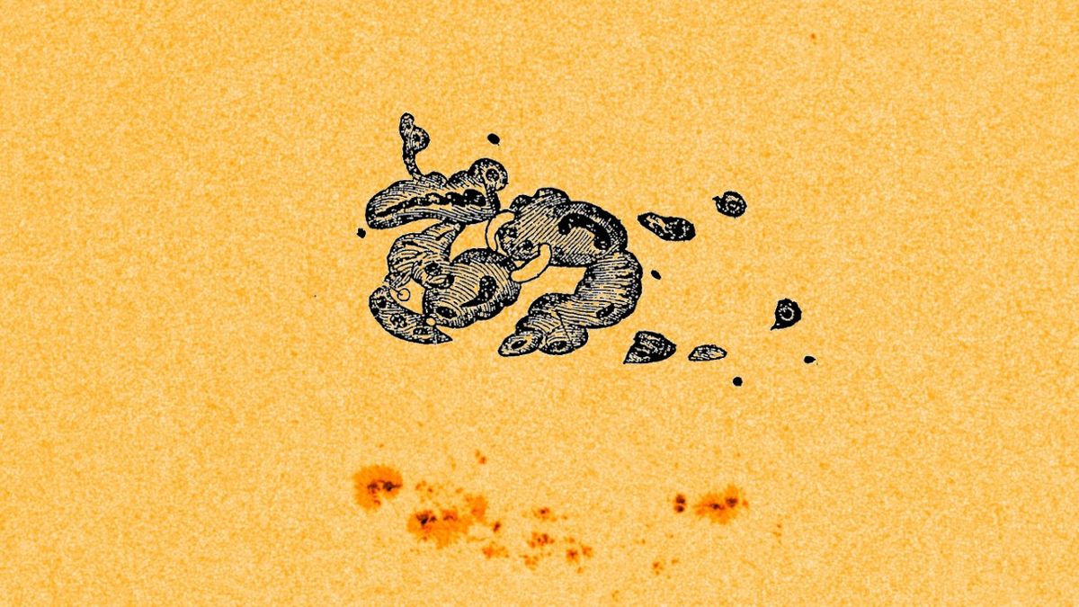
See the 'monster' sunspot that launched the Carrington Event, the most devastating solar storm in recorded history
What did the sun look like before the devastating 1859 Carrington Event? Sketches from astronomer Richard Carrington hold the answer.

AlaskanNoob
Solar Enthusiast
- Joined
- Feb 20, 2021
- Messages
- 957
I read that a big enough solar storm, as big as the Carrington event or bigger, could damage not only the power lines infrastructure but the electronics as well, computers, phones, our inverters, etc.
Is that true or just baloney? Can solar storms induce dangerous currents in small electric devices?
I have the same question. From the little I've gathered, while it may be possible, it seems unlikely. The Ben Davidson guy in the video posted earlier said it was possible but would take a much larger storm than G5. I'm not sure of his credibility though, some of the stuff he said in the video makes me question his credibility but I'm not a good judge of credibility in such discussions (still, he maintained instead of a faraday cage you should try to protect electronics by putting them in a root cellar or cave that was not made of metal which flies in the face of everything I've read).
Aridom82
Learning addict
Is kind of scary in a sense considering that our 'modern civilization' relies on development with very little flexibility or backup.I’m going to say no, though the fiction writers and doomsayers don’t find any interest in that.
Not that significant grid disruptions wouldn’t put a big dent in so-called “civilization”
We think of ourselves to be mighty and all but compared with the forces of nature our infrastructure is like a house of cards.
I would like to belive that my diy solar system could resist such an event and at least i could still have power at my house.
Aridom82
Learning addict
Well, you blew up my mind with your knowledge.It's not the DC current up one and down another of the three lines of the three-phase transmission line that's an issue. The three lines run close together and pick up essentially the same voltage along their length, like a twisted pair (they are actually a twisted threesome, essentially the same idea, with a one-third twist every few towers, to cancel out differences in the induced or capacitively coupled voltages.) The issue is DC (or ultra-low frequency AC) in the "common mode" - induced the same direction in all three wires and returning by a somewhat different path through the grounding.
The lines need a DC path to ground, to prevent the atmosphere's about 100v/meter vertical field from charging up the lines, as they run over hills or higher, to voltages that would arc over and damage equipment. So to a first approximation the typical long-haul transmission line is fed by three transformers in a Y configuration, with the center joint grounded. You have to ground it at both/all ends, so you don't have it "floating" when the breakers are open. So the three wires as a group act like a single long wire (see "phantom circuit") and the connection to the local ground at the ends completes the circuit.
Your main problem is with the long transmission lines that run intercity distances in close to a straight line. When the solar flare bombardment squeezes the earth's magnetic field, causing it to move relative to the transmission line, they pick up as much as about five volts per mile. Since the "squash" is wider than one face of the planet this just keeps adding up, mile after mile. Voltages are also induced in the ground under the wires. But the ground is non-uniform so it doesn't match the voltage of the wire above it and cancel out.
Since the squash lasts minutes to several hours the DC / low-frequency is "on" in a particular direction for a very long time, so the inductance of the transformer doesn't provide any limit to the current, which (in timescales of seconds) is determined just by ohm's law, the induced DC / low-frequency voltage (which becomes substantial over many tens of miles during a magnetic storm), and the line/ground/wire/winding resistance (which are all quite low). So if nothing is done about it you can get a substantial DC / low-frequency current in the windings.
Meanwhile there's a big AC voltage across the transformer from the generated power. The resulting current is limited by the inductance of the coils, and the coils are wound around an iron core, which increases the magnetic field, and thus the inductance (compared to a coil without such a core) by a large factor. But as the current rises the core can only become magnetized up to a point. Once it's fully magnetized (saturated) the inductance boosting effect disappears, and further increases in current only "see" the inductance of the coil as if it didn't have a core. So the current rise from a given increment of voltage is that same "factor of many" larger than when the core isn't saturated.
Transformers are built with enough core material to handle the normal currents from rated capacity operation plus a safety margin for typicl events. But in a geomagnetic storm, on a long transmission line, the magnetization from the current from the common-mode induced voltage adds to the cyclic magnetization from the line's AC. If the total is enough to saturate the core, you get massive spikes of current during some parts of the cycle, and this can quickly damage the transformer and/or the wiring or other equipment.
You can get the same effect on the neighborhood / rural distribution network if the drop transformers are Y connected - but it's not as pronounced, because the distances are shorter and there are ground connections at every "pole-pig" transformer.
But the real problem with the long transmission lines is that the house-sized substation transformers are custom-built, there isn't a big supply of them just waiting to be installed, even once you've got one it takes weeks to set it up, and one or two of 'em being knocked out can take out several small towns or much of a big city. If you fry a whole bunch of them at once, it could take months to years to get power back to much of the service areas.
The solution is to put something in those connections between the Y center and the local ground. A resistor to limit DC / low-frequency induced currents, maybe bypassed with a big capacitor to keep things running smoothly when the phases aren't balanced or one line has a fault, a current detector that fast-trips the disconnect, etc. These are big and pricey. But now that the issue has been identified the utilities have been adding such protection (sometimes voluntarily, sometimes due to government mandates) for years. As with the old Y2K problem, by the time we get a really bad mag storm or carrington event we might just have things fixed up enough that it won't be such a big deal.
Is there any books you would recommend for us?
Similar threads
- Replies
- 12
- Views
- 448
- Replies
- 9
- Views
- 517
- Replies
- 15
- Views
- 787
- Replies
- 3
- Views
- 398