diy solar

diy solar

92kW Lead-acid battery bank. Does it need equalising?

althemusicwizard

New Member
Joined
Jun 10, 2021
Messages
63
Hi.
This is a message I have sent to VARTA concerning their VARTA LFD230 sealed lead-acid batteries. I am awaiting their reply.

I have a solar battery bank consisting of 32 x Varta LFD230 12V batteries. The batteries are grouped in sets of 4 in series (to create 48V sets) and then the 8 sets are grouped in parallel. I have a battery monitor and note the voltage, capacity and expired Ah / kW daily. I use the meter to indicate what capacity the bank is at, as I run it only between 100% and 70%. If the solar doesn't keep it topped up above 70% then I charge the batteries from the grid.
I have had this setup since the beginning of the year. A full battery bank then was around 51.6V and a 70% depleted bank gave a voltage of around 48.5V. Over the last week I have noticed now, a 70% depletion gives a voltage of around 46V. This leads me to conclude that the bank may need 'equalising' to remove sulphate deposits. Would that be your understanding of the situation? I wanted to check that an equalisation program from my inverters could be run on these batteries without harming them. The inverters suggest a program default of 64V and the time can be set from 5 mins to 900 mins with a default setting of 60 mins.
Thanks for any help you may be able to offer.


Equalizing is essentially reserved for FLOODED lead acid where electrolyte can be replenished. SLA, AGM, GEL batteries generally can't be equalized without electrolyte loss and capacity reduction. In some cases, some manufacturers might publish a very limited equalization voltage slightly higher than the normal absorption voltage.

If you charge your batteries to 64V, you will destroy them.

If you are only charging to 51.6V, this is your problem as the batteries are never getting fully charged. Your charge voltage should be north of 56V.

I can't find a datasheet that lists charge voltages. What are the manufacturer recommended absorption and float voltages?
 
Equalization is hard on lead-acid battery, especially a valve regulated sealed battery. It is a matter of lesser of two evils.

The object is to minimize sulfation of lead-acid battery plates. When a lead-acid battery is discharged it creates a mossy brown lead-sulfate on plates. Over time, if left discharged, this mossy soft lead-sulfate will solidify into hard crystallize structure which cannot be recharged back to lead and sulfuric acid in electrolyte. Lead-calcium alloy plates can be left longer between recharging, about a month, compared to lead-antimony alloy plates used in deep discharge lead-acid battery which needs recharging within a week. Lead-calcium alloy plates have a lower self-discharge rate.

For 12v, six series cell lead acid battery, positive plates optimum float voltage is about 13.25v while negative plates need about 13.8v to keep sulfation from forming. So float voltage is a compromise.

Electrolyte fracturing into oxygen gas off the positive plates and hydrogen gas off of negative plates starts to get more vigorous at about 13.5 vdc of charge voltage. Continuously bathing positive plates in oxygen will accelerate corrosion of positive plate support grid. This increases battery series resistance.

With sealed battery that cannot add water you have to be careful of too much charging that creates gases. A small amount will be contained and recombine eventually. Too much gas pressure due to too high a charge level will cause venting which causes loss of electrolyte water.

Best compromise is to float at about 13.25v per 12v battery and do a full absorb to 14.2v about once a month or after a significant discharge of battery. This should minimize the need for equalization.
 
Thanks for those great replies Guys.
I contacted the seller of the batteries (I've contacted Varta as well and I'm awaiting their reply) and he suggested if I do equalise them to be gentle on them and for no longer than an hour. In response I suggested I could do them for 20 minutes and see what difference it made to the readings at 70% depletion. To be a little more accurate, what I've found is that starting from Jan 1st, the grid was kicking in to charge the bank every other day (the default on the Iconica inverters for lead-acid is when the bank falls below 48V, with the grid knocking off at 54V). This however resulted in the grid coming on and off every day or so and never getting up to 58.4V. After February I changed the grid to come on when the bank was 70% depleted, which meant in effect the batteries might start at 100% on day one, go down to 80% at the start of day 2, but if the weather was good, might end up back at 95% full. I did this type of 'yo-yo-ing' through February and had the grid kick in when the batteries showed 70% depletion. This meant in effect I only used the grid on about four or five occasions during February (my solar array is South facing and 8.4kW in size). I also changed the 'grid knock off' setting to 'FULL' which means the inverters' chargers gets up to 58.4V (at which time the amperage decreases from an inital rate of 150A to about 40A). It stays at this rate only for about ten minutes and then knocks off.

Reading RcinFLA's thoughts again, maybe this charge is too much? Though by my battery monitor measurements, if the grid knocked off around 54V, then the bank would only be about at 90% full? I can measure the Ah / kW going into the bank and about 18Ah = 1kW = 1% on the battery monitor. This amount is also confirmed by the grid meter in kWh consumed. Any more thoughts given that extra info?
Thanks
Al
 
Last edited:
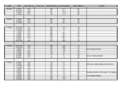
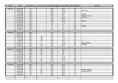
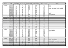
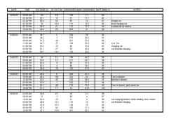
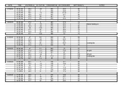
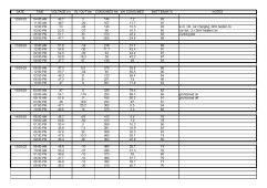
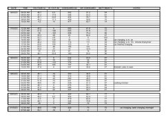
I managed to input the data that I have collected over the last 6 weeks that shows the performance of the battery bank.
The first 3 columns are self-explanatory. The 'IN/OUT' column is the amount coming from / going to the bank. A negative number means the bank is being charged, a positive number means the bank is supplying power to the demand. The 'CONSUMED' column is a running total of amp hours in and out of the battery. For a 70% depletion, this figure equates to around 560Ah. As the sun shines, the inverters put charge into the bank as well as meeting current demand. This forces the figure to return to 0 when the bank is full once more. The 'kW' is the total number of kW that have passed through the shunt from the bank.
If I compare the data from the 17th Feb at 8pm (ie. when there is no solar affecting the voltage), the bank depletion is around 73% and the voltage is 47V. Looking a month later at the 17th March, the bank is at a similar rate of depletion, 72%, but the voltage is now around 45.2V. There was very little solar this day evidenced by a draw out of the bank of 6A.
This is what leads me to believe the batteries may need equalising.
Any thoughts, anyone?
 
If the in/out Ah is a net number from a shunt, i.e., regardless of solar/loads the time of day doesn't really matter.

Here's what I see as relevant data points:

2/18: 95% @ 50.7V, 5.5A draw
2/21: 95% @ 50.8V, 5.2A draw (questionable due to the lack of documented absorption voltage)
3/2: 95% @ 50.7V, 7.4A draw
3/17: 90% @ 48.1V, 35.8A draw

I can't say that I see any significant difference in those data points that would indicate any degradation.

What I do see are days where your battery is not charged to full. IMHO, if you want to preserve the health of your batteries, you should ensure they are fully charged each day.

Additionally:

Review that your chargers are programmed properly.
You are charging with temperature compensation.
Ensure that all battery connections are properly torqued.
Ensure your bank is properly wired to the sources/loads (keeping an 8P bank sharing currents properly is nearly impossible without extra measures).
Check current flow through each string of batteries with a clamp DC ammeter under heavy charge and discharge currents.
 
Hi sunshine eggo,
Many thanks for taking the time to look over the data.
Sorry about the length of this reply.
I have used 35mm2 copper cable between individual batteries to create the 'series' 48V groups. These groups meet at three busbars (all equal length) of about 1m, then the busbars combine to another busbar of equal length (1m) then on to the 250A fusebox in a single length of about 1m.
The cable to the first busbar from the 48V groups, is in 35mm2 cable, from then on it is in 70mm2. I checked it as I was installing the groups and it appeared to meter in a balanced way, with no significant difference between 'groups' and no measurable loss between battery terminals and fusebox, each group measuring 51.6V upon installation. I have checked power draws up to 250A @ 50V (approx 12.5kW) and the cables stay cool to the touch so I'm pretty confident there is little internal resistance from the lugs or cables.

When you say, ensure your batteries are charged fully daily, I take it you mean at some point of the day, the batteries should be at 100% charge?
As we move into April (I should have stated I'm in Manchester, North England,UK), this may be possible, since my array size should be able to meet this. These are my inverters (Iconica 5000W 48V hybrid pure sine wave inverter with 6000W solar input, 80A MPPT solar controller and 100A mains charger, with parallel capability, no battery required):


The only way to have the grid kick in automatically, is when the setting in MENU 12 (page 17 of the pdf above) allows this. The next setting MENU 13 (page 18 of same manual) is when the inverters stop charging. Around the end of January I set these to 'FULL' as opposed to '54V' as I found through the data from the battery monitor, that the bank was never reaching anywhere like 100% charge. I think you're right when you say these settings are crucial to get right.

Of course, the reason for fitting all these things is because my energy costs have increased 600% since Sept 2021. I am trying to be as independent of the grid as possible, so usage of the grid to charge the batteries up every day seems counter-intuitive to this aim, although I do understand that this has to be balanced against degradation of the batteries. I recently installed 'smart meters' (MAR 8th) in order to have access to grid electricity overnight, at a third the price during the day. This only lasts for 4 hours however (between 00:30 and 04:30). My problem is that the inverters I bought have no programmable abilities other than what I wrote about MENUS 12 & 13 above.

HOWEVER.......I have had an idea that pulls upon the voltage drop experienced on a lead-acid bank when a sizeable current is drawn. I fitted three 5kW inverters in parallel to cover our 9.5kW electric shower. In this way, the 200A the shower pulls when operating is around 66% of the total system, which I find electronics seem to prefer rather than just having two inverters working flat out. I notice that the bank voltage can drop from anywhere between 1.2 and 2 volts, depending on how full the bank is AND how long someone is in the shower for. This has, on occasion triggered MENU 12 to kick in the grid and start charging the bank. What if I use this voltage drop to 'automate' my grid use?

I have ordered an unvented water cylinder which I will be fitting sometime in the next two weeks. It has dual immersion heater elements (3kW x 2) and will use about 12kWh to take water from around 20 degrees C, to around 62 degrees C. My idea is that I can fit timers to these immersion heaters and coupled with the timer on my Nissan Leaf car, I can time a 9kWh power draw from the bank between the hours of 00:30 and 04:30. If I set MENU 12 to be somewhere around this voltage drop figure, then in winter (NOV-FEB) I can draw upon cheap overnight grid electricity to charge up the bank AND give us a 200L tank of hot water for the next day. The 30kWh I have available from my bank (ie. 100-70% depletion), can then be focused upon providing cooking and some background heating before rinsing and repeating every night.

Thanks for all your help so far.
Al


I understand the limitations, but limitations and decisions have consequences. The less time lead-acid batteries spend at 100%, the faster they will degrade.

Ideally, you should be replenishing your daily usage with solar. I understand that as a resident of the UK, our star is hesitant to show its face, particularly in the winter.

When you can't replenish with solar, if there is a time of day where your grid power is "cheap," then you should use it to charge at that time.

What little info i can find on the batteries do not impress me for longevity in general. I expect you'll be lucky to get 3-5 years out of them.

When pulling 200A, what is the current passing through each of the 8 strings?
 
'When pulling 200A, what is the current passing through each of the 8 strings?'
I'd have to check that. As you can imagine, having 32 x 240Ah batteries (each weighing 56kgs) was an engineering feat in itself, if I do say so myself. Getting a clamp meter in place is a little difficult but doable. I think you're right about the 3-5 year lifespan, but they are a glass mat battery so we'll see. As it is, I paid a third the price of them retail, so I've taken a gamble. This is all new to me on this scale, having previously only dabbled with panels and inverters on camper vans.
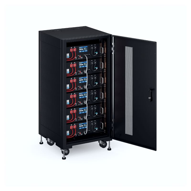
One of the reasons I want to install the unvented cylinder is so we only use an electric shower for emergencies. The unvented cylinder will probably be 'charged' using just one immersion heater running at 3kW, with the second one running when needing a boost. That way the batteries and inverters aren't pushed so hard. I can imagine in the future replacing the bank with something like a Lipo server type bank such as this:
 
'When pulling 200A, what is the current passing through each of the 8 strings?'
I'd have to check that. As you can imagine, having 32 x 240Ah batteries (each weighing 56kgs) was an engineering feat in itself, if I do say so myself. Getting a clamp meter in place is a little difficult but doable.

Anywhere on a single string should get you a good reading.

I think you're right about the 3-5 year lifespan, but they are a glass mat battery so we'll see.

AGM have shorter service life than flooded.

As it is, I paid a third the price of them retail, so I've taken a gamble. This is all new to me on this scale, having previously only dabbled with panels and inverters on camper vans.

If you got a smokin' deal, then they were probably worth it.

One of the reasons I want to install the unvented cylinder is so we only use an electric shower for emergencies. The unvented cylinder will probably be 'charged' using just one immersion heater running at 3kW, with the second one running when needing a boost. That way the batteries and inverters aren't pushed so hard.

Should help. You UK folks and your instant hot water heaters make for some pretty brutal AC consumption.

I can imagine in the future replacing the bank with something like a Lipo server type bank such as this:

Lipo usually means lithium-polymer, which is typically a different chemistry. Given the nominal voltage, those are Lithium Iron Phosphate, LiFePO4 or LFP.
 
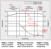
Interestingly, today we had some good solar and the bank did something I hadn't seen before. I had charged it up overnight so that by 7.30am it was sitting at 99% and around 52.6V. The solar lasted for five or six hours (between 9am and 3pm) at a really good output from 2-5.5kW per hour. After the bank got back to 100%, it kept saying around -35 to -40A on the meter, meaning there was still some current going into the bank. This carried on with the bank voltage rising to 58.4V, where it stayed for a couple of hours (a bit like equalising). After this it dropped to a float voltage of 54V where it stayed for the rest of the day. I will follow sunshine ego's advice from now on and if the bank doesn't get up to 100% during the day through solar charging, then I'll instigate a grid charge to kick in during the night.
Many thanks for all your help.
 
What you describe sounds like a normal and proper charge.

100% can also be misleading. A battery monitor may not correctly reflect true 100% SoC due to the inefficiency of lead-acid charging.

Charge profile:

1679512115563.png

With 8 strings, you have 230Ah * 8 = 1,840Ah

0.02C = 0.02 * 1840 = 36.8A

So your battery isn't truly at 100% until 58.4V is attained and held until the current drops to 36.8A or lower.

It sounds like your charger is handling it properly, so if you note that the charger is in float mode, you can be reasonably confident that the battery is fully charged - not just by the 100% indication.
 
Back
Top