diy solar

diy solar

Autotransformer for 120 to 240, and 240 to 120

LakeHouse

Solar Enthusiast
Joined
Dec 1, 2022
Messages
359
Location
Western Canada
Looking for a sanity check on buying a Victron Autotransformer for an existing system, and then later repurposing it for a future system upgrade...

Current system is completely off-grid, 48Vdc with an AiO outputting 3.5kW of 120Vac. I would like to be able to run a heat-pump clothes dryer like this one, which has maximum power draw of 2500W, but requires 240V.
So my thought is to install a Victron 32A Autotransformer that would (currently) be used only to run the dryer. I realize that running a 2500W dryer on a 3500W AiO leaves me little overhead, but I'm not very concerned about that for now.

At some point down the road, the plan would be to replace the AiO with an separate SCC (this is purchased and just needs to be installed in the spring), and a 48Vdc, 5kW 230Vac Phoenix Inverter. The '230V' version of the Phoenix can be set to output 240Vac, which would be fed to a panel that would power the dryer (and any other future 240V loads) and the Autotransformer, which would now be repurposed to step-down the 240V to 120V to feed the existing 'main' distribution panel for the cabin.

Any see any glaring issues with this plan?

Nope. you will need to ensure the grounding and N-G bond is appropriate.

Why the Phoenix instead of the Multiplus?
 
you will need to ensure the grounding and N-G bond is appropriate.
Agreed. This is at least part of what I'm questioning with the setup; what is neutral for the 240V side? Since this isn't exactly split-phase, but rather just 240V and 120V, the 'neutral' on the 120V side and 240V side isn't the same. So I think I end up with a N-G bond for each independent neutral?

Why the Phoenix instead of the Multiplus?
Hmmm, this is a good question. I had in my head that the Phoenix was cheaper, but it looks like that's not the case, or at least not anymore.
I don't think there's anything specific that the Multiplus does over the Phoenix that I need; I'm off-grid and have other methods of charging the batteries from a generator if required, so the 'charger' functionality is unnecessary. But for the same price (or less, currently), the Multiplus seems like a more capable device.
 
This is at least part of what I'm questioning with the setup; what is neutral for the 240V side? Since this isn't exactly split-phase, but rather just 240V and 120V, the 'neutral' on the 120V side and 240V side isn't the same. So I think I end up with a N-G bond for each independent neutral?
The more I think about this, the more I'm leaning towards thinking this won't work as planned (i.e., with a 240V inverter). I wouldn't be able to wire a split-phase NEMA 14 outlet, because there will be no 'neutral' that will be half-way between the two wires coming out of the inverter, and I don't think the Autotransformer can help with that.
But... If I go with a 120V inverter, then the Autotransformer can provide the split-phase I want on the 240V side.
 
It can work. You just have to pay attention when you switch configurations.

Neutral is always 120V from a 240V leg, and ground is always 0V from neutral :)

Must only have one N-G bond anywhere.

120VAC in to AT 120/240 output has provisions for shifting the N-G bond from the inverter to the AT, but can be used either way OR externally.

230VAC in to AT 120/240 output demands the N-G bond be handled at the AT OR externally. Inverter would have the N-G relay permanently open and the case would be grounded. This is pretty common when folks want a big 240V inverter.

The extra charger may not be needed... but... :)

Only downside to the AT is a 28A max imbalance between 120V legs.

@timselectric to check if I'm full of shit... :)
 
230VAC in to AT 120/240 output demands the N-G bond be handled at the AT OR externally. Inverter would have the N-G relay permanently open and the case would be grounded. This is pretty common when folks want a big 240V inverter.
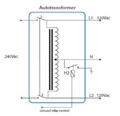
Ah, this makes sense! I think I see where I was getting tripped up on how this should work... I was thinking that I'd somehow run my split-phase appliances directly off the inverter, but that isn't correct... I'd run the inverter into the AT and then run everything off the AT output:

1705698413518.png
So the only thing connected on the left side of the diagram is the inverter, which is case-grounded but definitely not N-G bonded, and the inverter 'N' connection isn't actually 'neutral' at all as far as any loads are concerned.

Thank you @sunshine_eggo! This was very helpful.
 
Ah, this makes sense! I think I see where I was getting tripped up on how this should work... I was thinking that I'd somehow run my split-phase appliances directly off the inverter, but that isn't correct... I'd run the inverter into the AT and then run everything off the AT output:

View attachment 189962
So the only thing connected on the left side of the diagram is the inverter, which is case-grounded but definitely not N-G bonded, and the inverter 'N' connection isn't actually 'neutral' at all as far as any loads are concerned.

You got it.

230 input is N to AT L1 and L to AT L2.
The AT provides the center-tapped N AND CAN handle the N-G bond if you want to, or at the panel.

If you're totally off-grid, it makes more sense to me to provide the N-G bond at the panel. when charging with a generator, the N-G bond breaks because that's the normal behavior when AC input is detected, and I don't think that can be over-ridden.

If it's at the panel, you simply need to program everything to have it's relay open, and you're good to go, and you retain the N-G bond when powered by generator.

Happy to help! I'm hell bent on smurfing people into smurfs until ALL of us are smurfs!
 
I'm hell bent on smurfing people into smurfs until ALL of us are smurfs!
I'm well on my way. I built the original system last spring with a BMV as the only Victron component, and I've currently got a 150/45 SCC and VRM on a Raspberry Pi ready to install once I can access the house in the spring, with future plans for a Victron AT and inverter in the future.

And now that I know what I'm looking for, I just found that Victron has a wiring schematic for a setup pretty much exactly like what I want to do. Because, of course they do!

Yes. Their schematics are luscious. When you first look at them, it can be overwhelming because it feels like there's too much information, but when you just methodically go through it, read the notes in the boxes, and follow the wires, it really starts to click.
 
I'm well on my way. I built the original system last spring with a BMV as the only Victron component, and I've currently got a 150/45 SCC and VRM on a Raspberry Pi ready to install once I can access the house in the spring, with future plans for a Victron AT and inverter in the future.

And now that I know what I'm looking for, I just found that Victron has a wiring schematic for a setup pretty much exactly like what I want to do. Because, of course they do!
How has this been going for you?.. I had I similar idea I discussed with a friend who is an engineer and I'm not sure I can word it as well as he did, but he basically told me to never step up voltage from source, only step down. He said the equipment would overheat and reduce its lifespan. Something about going over VAR calculations of the equipment
 
How has this been going for you?
The 150/45 and VRM are fantastic.
I haven’t built the rest yet, and may not for a few more years.
but he basically told me to never step up voltage from source, only step down.
I actually wasn’t planning on using the transformer to step up, just center-tap 240Vac to get 120V split phase.
Electrical utilities step ac voltage up and down with transformers all the time, so I’m not sure I understand your buddy’s concern, other than that Autotransformers do have limitations on acceptable power factor (different kind of unit, but measuring the same thing as VAR), and I would be inclined to stay within those limits.
 
Back
Top