diy solar

diy solar

Battery isolator between battery and inverter

Yes, you should have a suitably rated disconnect (switch or breaker) and a fuse between the battery and inverter. Not to avoid the sparks, but to improve safety and to make maintenance easier. You can avoid the spark caused by the initial inrush current by using a low value resistor to pre-charge the inverter's capacitors prior to connecting your batteries.

The switch you linked to doesn't specify a rating for continuous current, though it looks good enough. You'd want to do a stress test while monitoring it's temperature first to be sure it's safe for the long term.
as someone with a similar project, can you explain how to do fit the resistor please?. where would it be fitted, how is it best to achieve it? or can you point me me to a suitable resource where i can learn about the whys and wherefores please, thanks
 
as someone with a similar project, can you explain how to do fit the resistor please?. where would it be fitted, how is it best to achieve it? or can you point me me to a suitable resource where i can learn about the whys and wherefores please, thanks
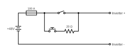
You'd place the resistor in parallel with the disconnect switch, with its own momentary switch. That way while the big disconnect switch is in the "off" position, you can hold the momentary switch for a few seconds, completing the circuit through the resistor to pre-charge the inverter's capacitors. Then you let go of the momentary switch and turn your high-current disconnect switch to "on". Your fuse would be in series with the disconnect switch.
 
You'd place the resistor in parallel with the disconnect switch, with its own momentary switch. That way while the big disconnect switch is in the "off" position, you can hold the momentary switch for a few seconds, completing the circuit through the resistor to pre-charge the inverter's capacitors. Then you let go of the momentary switch and turn your high-current disconnect switch to "on". Your fuse would be in series with the disconnect switch.
Isn’t there a risk that someone pressing the momentary switch with the disconnect switch in the on position would short the battery?
 
circuit(1).png

Here you go. The switch in series with the 20R resistor is a momentary swtich for pre-charging the capacitors, the other is your high-current toggle switch.
The momentary switch wouldn't need to be high current type, 5A would be sufficient.
 
View attachment 122921

Here you go. The switch in series with the 20R resistor is a momentary swtich for pre-charging the capacitors, the other is your high-current toggle switch.
The momentary switch wouldn't need to be high current type, 5A would be sufficient.
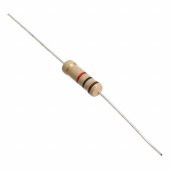
would the resistor need to be a standard one like this one
1670182793256.jpeg

Or specifically rated to higher currents?
 
would the resistor need to be a standard one like this one


Or specifically rated to higher currents?

It's easy to do the maths:

V (voltage) = I (current) × R (resistance)
P (power dissipated) = I² (current) × R (resistance)

In the case of a 52v battery voltage and 20 ohm resistor:

52v = I × 20Ω
I = 2.6A

P = 2.6² × 20Ω
P = 135.2W

On this basis, the 0.5W resistor you've provided a picture of wouldn't stand a chance.
But the situation isn't that bad:
  • The resistor doesn't need to provide continuous power, just for a few seconds.
  • The capacitor's voltage will quickly rise from 0v, so the above calculations only apply for the first tiny moment of surge.
Because of this, a cheap 20W ceramic resistor would work just fine.
Just ordered a 30 Ohm 25W resistor https://www.ebay.co.uk/itm/26546006...ar=565276352330&widget_ver=artemis&media=COPY
 
I am looking at buying one of these battery isolator switches for my 24v MPP 3.6kw system, switching 8 x 272v lithium batteries. Did the switch you bought work? One of the feedbacks was regarding the high voltage drop, and others complained of overheating.
I would appreciate any recommendations for other fused switches between battery and inverter 250amp. Thanks
Yes, I first bought the one from Amazon but then returned because it was becoming very hot at 50A. I ended up buying the Victron one which is much better
 
Yes, I first bought the one from Amazon but then returned because it was becoming very hot at 50A. I ended up buying the Victron one which is much better
I did buy one and have had to change it as well they are not suitable for our use.
 
Back
Top