Comments on this setup?View attachment 5001Could this work?


You are using an out of date browser. It may not display this or other websites correctly.
You should upgrade or use an alternative browser.
You should upgrade or use an alternative browser.
BMS common port vs seperate port
- Thread starter Newenough
- Start date
Comments on this setup?
Upgrade ... "only when charger is on" version (and corrected NC to NO)

Buzzard Bait
New Member
- Joined
- Dec 15, 2019
- Messages
- 35
Hi you have asked an interesting question. It sounds like you are considering bypassing the SCC and going straight to the BMS thru the charge port on the BMS. I think the BMS could regulate small differences in the incoming charge, but as for my system the voltages would be too far out of range of the BMS, and as a result the BMS would rarely allow any charge to the battery. I will be interested to learn, what you find out. Good luck, and I hope you see no magic smoke.I am learning here myself but it seems like the C- could be used to disconnect ground from the solar array in order to block the solar from further charging. The charge controller would still be connected to the battery. The voltage and current from the solar array is variable so you would need to make sure the BMS could handle any extremes. I haven't tried this and may be missing something.
I called Midnite Solar and asked if the Midnite Classic 150 would be damaged if the battery were to be disconnected while the PV array was supplying power. They said it would not be an issue for the Classic because the controller simply shuts off when disconnected from the battery. So, it depends on what solar charge controller you are using I guess.Most people that i talked to said that when you cut off the batteries from the Charge Controller while the solar panels are connected will surely damage the controller.
Hi all!
I have a 8 cell 24v system under construction. Using the Victron MPPT (100/30) and Smart BatterySense for low-temp cutoff.
I have the Daly 100A common port ordered, but I worry about what happens if the BMS will do a cutoff (low voltage for example) if I have both load and charge through the BMS.
But, what if one would put a 24v relay on the negative from the charger, so when the relay has power the charging will go through the BMS, but if the BMS does a cut-off the relay would switch the negative from the charger directly to the battery (and bypass the BMS)?
Then the battery would be charged although the BMS did a low voltage cutoff, right? And when the BMS goes back online then the relay would would be powered and switch the negative back through the BMS.
What do you all think?
Attachments
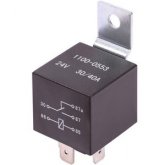
Sorry about that ..I'm confused, you ask about using 2x common port bms but you show a picture of a separate port bms and a relay.
You are tweaking my OCD.
nosys70
Solar Enthusiast
- Joined
- Jan 15, 2020
- Messages
- 839
if you get a dry contact on your device you could probably use it.
all the problem with such system is not in the logic of the drawing, it is in the way it really works.
BMS is switching way faster than a relay, so you can probably expect to have a short period where your differents switches are not
in the status you expect (bms and relay disconnected or worse bms and relay connected)
In addition , i doubt a relay can sustain switching so many amps very often.
nosys70
Solar Enthusiast
- Joined
- Jan 15, 2020
- Messages
- 839
in fact i am in the same situation, i purchased a mppt as per advice of Will's site , with the intent to use LiFePo4 battery and solar panel.
2400W mppt, minimum 300A 24V 2P8S battery (to be purchased). I already got the mppt, and 2 daly BMS 200A (common), and got 10x 24V 250W PV. (for instance will use only3 or 4 in parallel, so about 30-40Amps available ). I think i could install the the PV in series (it seems the MPPT suport up to 170v on Panel input), but i prefer to mount them in paraller for better efficiency.
Now , i am reading this thread whith this warning (WTF ! burning the MPPT ?) about BMS disconnecting battery when low (while i do not really understand in which situation this could cause a problem, since if battery goes low, it is because solar panel are not giving power (at night) or not enough (big load) and in that case if BMS disconnect, PV power will either be null (at night) or be absorbed by the load.)
I think if you reach the point when system is in use (with AC + PV not able to fulfill the load) so draining slowly the battery until the point it disconnect, it means your system is undersized at some point.
but yes, better safe than sorry, would be great to have some solution.
my opinion is you could put a pair of battery and have the relay switch the battery, so if one BMS cut, the other battery would take over.
(jus making sure the relay is avoiding both battery in parallel to avoid an empty battery reconnecting with a full battery).
I do not see really the point to expect the empty battery to be charged (a way of another) at this moment, because if you were in a situation where need to drain the battery low enough to have the BMS disconnecting, i do not see where you would find the energy to charge the battery.
in that case it would mean you battery capacity is too small for the load or your PV are too small to sustain charge+load.
Another way would be to limit the MPPT to disconnect the load way before the battery level triggers the BMS.
If you reach the point where your BMS disconnect the battery, i think you can save the few extra minutes by disconnecting the load first.
Last edited:
Seems like it should work to me. As mentioned by another there may be a momentary drop in voltage during the switch but I would think the MPPT could handle that. I haven't tested that though.Hi all!
I have a 8 cell 24v system under construction. Using the Victron MPPT (100/30) and Smart BatterySense for low-temp cutoff.
I have the Daly 100A common port ordered, but I worry about what happens if the BMS will do a cutoff (low voltage for example) if I have both load and charge through the BMS.
But, what if one would put a 24v relay on the negative from the charger, so when the relay has power the charging will go through the BMS, but if the BMS does a cut-off the relay would switch the negative from the charger directly to the battery (and bypass the BMS)?
Then the battery would be charged although the BMS did a low voltage cutoff, right? And when the BMS goes back online then the relay would would be powered and switch the negative back through the BMS.
What do you all think?
nosys70
Solar Enthusiast
- Joined
- Jan 15, 2020
- Messages
- 839
actually the fear is not with the drop, but with the PV voltage going mad since the battery suddenly disconnect.
you can probably limit the risk by using low voltage panel set up (meaning, you use about the same voltage for the PV input than the battery, so 24V panels for a 24v battery)
for sure if you have 150v PV voltage and only 24V battery, all is fine if the MPPT can discharge into the load or the battery, but if suddenly the battery disconnect, there is a chance to have a big voltage surge ( and mosfet don't like this, while they can easily sustain a current surge, after all they are designed for this)
Last edited:
If you bypass the BMS for charging you end up bypassing low temp charging cutoff.
If you connect the charger through the BMS, you will not charge in the event of a low voltage situation.
Does anyone know if I can just use 2 common port bmss'. (Programmable, so that you can set different parameters for each) Connect one to loads and the other to supply?
If you connect the charger through the BMS, you will not charge in the event of a low voltage situation.
Does anyone know if I can just use 2 common port bmss'. (Programmable, so that you can set different parameters for each) Connect one to loads and the other to supply?
WaltDownunder
New Member
- Joined
- Feb 6, 2020
- Messages
- 3
View attachment 665
Also, I posted this elsewhere sometime ago:
Quick update for advanced LiFePO4 raw cell systems using a Daly BMS:
On my website I recommended using a separate port BMS for over voltage protection for the mppt connection (if common port BMS is used, possibility of destroying mppt during low voltage disconnect).
Well yesterday, a viewer and I finally received our separate port BMS from Daly, and the amp rating was not as advertised on the listing. The separate port can only handle 10 amps!
Considering the likelihood of over voltage situation from most high quality mppt, and the chance of matched LiFePO4 cells going out of balance is rare (and BMS will correct for cell drift over time), and that LiFePO4 can be over charged to 4.2v per cell before electrolyte degradation... I would say its safe to connect mppt directly to the battery bank, and bypass the BMS entirely. We have been doing it this way for years, but people still want to use a BMS.
I would say use BMS for loads, and not for chargers. If you have mismatched cells, and some hit a higher voltage at high SOC quicker than others, drop the upper limit voltage of your controller. 14.0-14.2v is a safe charging voltage that can give full capacity with LiFePO4 12v.
I hope this helps! I bet most people building these systems will figure this out when they see this problem, but if you are a beginner trying to build an advanced level system, then this bit of information will be very useful. Let me know if you have any questions
Thank you Will, very useful.! So simply connect the BMS to the DC distribution point (load bus) and charger directly to battery (charge bus) ? In my application on a boat, I charge with solar and alternator. See my post in the forum under "marine". My concern is that if the BMS fails, the abrupt disconnection would damage the diodes of the alternator.
In the Youtube video for DIY LiFePO4 you recommend using the .APK file "below" for the BMS/balancer with bluetooth, instead of the APK on the seller's site. but there is no link that I can see. Can you please direct me? Also, the balancers only with small LCD that you show would be useful. Can you please give links?.
Capt Bill
Sailing Options
As a newbie to this BMS learning curve for DIY LifePO4s, I am wondering: What does" SCC" stands for? I study this full thread as see it I can figure that out.The big problem with separate port BMS is the current is extremely limited. Not uncommon for a 100a separate port bms to have a charge line that can only handle 8-15 amps. If you are building a system for solar, use a common port for your loads, and connect the SCC directly to the battery.
Last edited:
Solar Charge ControllerAs a newbie to this BMS learning curve for DIY LifePO4s, I am wondering: What does" SCC" stand for?
As a newbie to this BMS learning curve for DIY LifePO4s, I am wondering: What does" SCC" stands for? I study this full thread as see it I can figure that out.
Svetz has put together a list of commonly used Acronyms here
Easty
New Member
- Joined
- Apr 9, 2020
- Messages
- 13
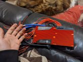
This is an interesting discussion. I originally ordered the separate port and realized in the difference in charge/load values later. As I'm scaling up the batteries in the future, I ordered a new common port BMS 16s 48v 200ah and it just arrived. This thing is huge, 2x the size of previous BMS. I actually had a bypass for when using my 240v welder and plasma cutter. With this one I'm going try and see how much current I can draw through it.
It also looks different than pictures shown on the sellers site. It has double 6awg p- and b-.
It also looks different than pictures shown on the sellers site. It has double 6awg p- and b-.
Attachments
MisterSandals
Participation Medalist
There are a couple we (unfortunately) need to add:Svetz has put together a list of commonly used Acronyms here
- LiFePo4 - Lithium Iron Polonium(IV).
- LifePO4 -
 Phosphate.*

Too picky?
dashdrum
New Member
Mikey likes it!There are a couple we (unfortunately) need to add:
*View attachment 10679
- LiFePo4 - Lithium Iron Polonium(IV).
- LifePO4 - View attachment 10678 Phosphate.*
Too picky?
Hearing that dual port BMS have different charge and discharge limits is disheartening...
I can charge around 4Kw/h from solar and we will ignore the current from a DC generator ....
One would hope that a dual can accommodate 100A on both ports
I can charge around 4Kw/h from solar and we will ignore the current from a DC generator ....
One would hope that a dual can accommodate 100A on both ports
Similar threads
- Replies
- 1
- Views
- 110
- Replies
- 3
- Views
- 326
- Replies
- 0
- Views
- 262