diy solar

diy solar

BMS question regarding parallel

Texas-Mark

Solar Addict
Joined
Aug 4, 2021
Messages
1,408
For simplicity, assume a 12V battery bank composed of 8 cells.

Since some people have said that it is not ideal to have cells in parallel (for BMS monitoring), and that it is better to monitor cells individually, how do you do that with 8 cells. Is it possible with a single BMS?
 
With 8 cells and a single 4S BMS, to the best of my knowledge, it is not possible to individually monitor each cell.
 
That is what I thought.


Yes, I knew a 4S BMS would not do it. I was wondering if they made a 4SxP version just for this type of thing.
I have heard hints that some of the higher-end BMSs like REC or Batrium might be able to do this, but I have never looked into it so I could be wrong.
 
oopsie about my mixup,

4SxP BMS unknown type for me.

accurately and separately measuring the voltage of two cells paralleled by busbar is difficult. do not know of a way around that.

edit: oops it seems i need coffee. you’re asking about two strings paralleled but one BMS. have not seen any models that monitor two or more sets of cells like that.
 
Last edited:
you’re asking about two strings paralleled but one BMS. .

Right. I have seen some people say that using BMSs in parallel is not a good idea. I don't agree with that, but what other option is there other than paralleling the cells, which some people also say is not a good idea, since you can not monitor individual cells.
 
Since some people have said that it is not ideal to have cells in parallel
Some people also say running 2P4S is just fine, especially when they want to use a single BMS.

Matching cells so the pairs are as equal as possible helps quite a bit. I match strongest with weakest cell, second strongest with second weakest,…
It’s been working perfectly thru hundreds of charge/discharge cycles (over 500 and nearly 2 years).
 
Thanks everyone. I just wanted to make sure there was not an inexpensive BMS that was designed for this configuration. I'm sure there is more to it, but I was thinking it could be as simple as having a second set of sense wires that also reference (internally) to the main negative post. Like a 8S BMS that has a switch that turns it into two 4S stings.
 
this may not help. but it does sort of depend on how you would like the system to behave when one of the packs needs to disconnect. full disclosure: i want the system to be able to limp on one pack, but not everyone does.

going to use one JBD FET BMS per pack and parallel the packs at main busbar, each pack fused appropriately of course.

the JBD has a simple two wire “switch” input that allows an external switch to turn off the BMS.

ensuring the BMS don’t reconnect with significantly different voltage as neighbor pack is a primary goal.

one way would be to force all other pack to disconnect whenever any pack disconnects. can be done with microcontroller and tiny relay.

allowing one pack to carry on after another pack disconnects is more complicated but i am intent on engineering it properly. basically without junking up your thread too much, my flavor of crazy involves a single contactor and DC-DC converter per pack. when a pack disconnects for low voltage, it will stay offline. when power is available the DC-DC converter set to 14.0V will charge the pack separately and when all other packs are also within margin it would be reconnected. i don’t think this is appropriate for most people here but it’s worth mentioning i guess. all this would be executed with the help of a microcontroller running custom firmware that i must write

basically if they act rationally in lock step the big bad problems go away with parallel BMS.
 
Right. I have seen some people say that using BMSs in parallel is not a good idea. I don't agree with that, but what other option is there other than paralleling the cells, which some people also say is not a good idea, since you can not monitor individual cells.
Many systems are built with cells wired in parallel. (Every EV on the market has parallel cells)
Many systems are built with BMSs in parallel.

Neither approach is wrong...both approaches can be made to work. It all depends on the particular system, budget, and designer's preferences.


In the DIY space, the reason not to run cells in parallel is that you can't monitor individual cells. (I don't generally feel a need to monitor individual cells but others might.

The main reason I have seen for running multiple BMSs in parallel is to get higher currents. When the system needs above ~150A out of the battery, finding a single BMS to handle it can be a challenge.

I will run cells in parallel if I can, but if other factors like max current prevent a single BMS.. I will look at multiple BMSs in parallel. However, when a design get into high currents like this, I start looking at BMSs that can control the loads and chargers either through signals or through communications channels....These are not nearly as current limited so that will allow parallel cells and high current.
 
Many systems are built with cells wired in parallel. (Every EV on the market has parallel cells)
Many systems are built with BMSs in parallel.

Neither approach is wrong...both approaches can be made to work. It all depends on the particular system, budget, and designer's preferences.
??
 
Thanks everyone. I just wanted to make sure there was not an inexpensive BMS that was designed for this configuration. I'm sure there is more to it, but I was thinking it could be as simple as having a second set of sense wires that also reference (internally) to the main negative post. Like a 8S BMS that has a switch that turns it into two 4S stings.
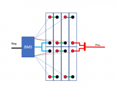
On the surface, it seems like that would be a reasonable idea. Something like this.

1634502500442.png

I can think of no technical reason a BMS like this could not be designed and built. However, the number of voltage sense and balance circuits would be doubled. The power fets, PC board and some of the control logic would be shared. It would be cheaper to build this than two BMSs but it is probably going to cost quite a bit more than just one traditional 4S BMS.

This would allow for the monitoring of individual cells, but it does not address the other reasons people use multiple BMSs
* Increasing system current
* Redundancy.

So, the only reason folks would opt for a product like this is to monitor individual cells. However many folks would still go with multiple BMSs for other reasons... which leaves a big question mark on the market size for such a BMS.

For DIY there may be a niche market for this, but my guess is a commercial product manufacturer would be using a single larger cell rather than two smaller cells. If they are using multiple smaller cells, they will probably be grade A cells that really don't need individual monitoring.
 
I can think of no technical reason a BMS like this could not be designed and built. However, the number of voltage sense and balance circuits would be doubled.

How is that any different than a 8S BMS? They all use some sort of "voltage ladder" to measure the cells. Yes, there is probably a bit more to it, but I could see making one that could do either with a flip of a switch to change the 0V reference point.

Now I can see having two strings parallel on the same BMS causing some erroneous cell readings, since one string could be "forcing" the voltage on the other string to perhaps some incorrect values.
 
How is that any different than a 8S BMS? They all use some sort of "voltage ladder" to measure the cells. Yes, there is probably a bit more to it, but I could see making one that could do either with a flip of a switch to change the 0V reference point.
You are correct. Assuming most of the control logic is in SW, it would probably cost about the same as an 8S BMS to build a 'dual-4s BMS'. The software and any related Bluetooth app would require significant updates to handle two strings. Any logic that is implemented in HW could get very complicated if it has to operate in two different modes.

Now I can see having two strings parallel on the same BMS causing some erroneous cell readings, since one string could be "forcing" the voltage on the other string to perhaps some incorrect values.
The only common points between the two strings is the most positive and most negative terminals. I am not sure it would be much different than two batteries (with 2 BMSs) in parallel.
 
The only common points between the two strings is the most positive and most negative terminals. I am not sure it would be much different than two batteries (with 2 BMSs) in parallel.

I was thinking if one had really bad cells in one string. the other string could be artificially bringing the voltages up to match it. But I guess you are right since two BMSed strings would also be tied together at both positive and negative ends too and result in the same thing. Maybe that is one reason some frown on doing it that way.

I guess no matter what, whether you are paralleling cells or strings, there will be a downside.
 
Last edited:
I guess no matter what, whether you are paralleling cells or strings, there will be a downside.
Engineering is the art of trade-offs. Cost, quality, reliability, functionality, etc. A decision on one will almost always have an impact on the others.
 
Back
Top