Self host your MQTT server on a PI.How do I sign up for MQTT.
Is this the right platform? HiveMQ Cloud Free Plan
You are using an out of date browser. It may not display this or other websites correctly.
You should upgrade or use an alternative browser.
You should upgrade or use an alternative browser.
CAN and RS485 BMS Interface with multiple emulated Inverter protocols for JkBms Jbd BMS Daly 123Smart
- Thread starter mrconstantin
- Start date
MarcelVo
New Member
Thanks for your reply, I do have a bunch of Rasp Pi's and Uno's but ESP32 is new to me. Will order the parts you listed and build the setup and let you know once I have got in all in place and connected. Thanks for the help.
Hi Constantin, hope you are fine. If you would have time to provide the key for the ESP and fake config for the provided data it would be great, thanks MarcelFound a nifty device called “USB Tin” on Amazon, which comes with a win app “USB Tin Viewer” which allows me to view data coming out of the inverter, confirming its pin 2-CanH, pin 3-CanL and 4-GND, so that part is also resolved. Still see nothing in the info part of the app, when connected like that, but could also be because key is missing; chip ID is 9629e748 I do see the ESP sending data on the CAN so confirm that also works. Awaiting further instruction. Thks MarcelView attachment 182321View attachment 182322
Peter Laub
New Member
I built the circuit with an MCP 2115, a SN 65HVD230 and a MAX 485. I want to use it to control an inverter, a JK BMS and two JK balancers. The ESP is running, but so far it is not connected to the JK. The BMS does not connect over Max 485, the balancers not over CAN. I measure DC voltage:
Balancer...H ground 2.5V+ L ground 2.5V+
ESP pin D4-Ground 3.56V+ D5-Ground 3.56V+
Does anyone have a suggestion
Balancer...H ground 2.5V+ L ground 2.5V+
ESP pin D4-Ground 3.56V+ D5-Ground 3.56V+
Does anyone have a suggestion
Peter Laub
New Member
gfjardim
New Member
Hi, I want to evaluate your software, my chip id is
Thanks in advance!
f565b7a0
Thanks in advance!
Peter,I built the circuit with an MCP 2115, a SN 65HVD230 and a MAX 485. I want to use it to control an inverter, a JK BMS and two JK balancers. The ESP is running, but so far it is not connected to the JK. The BMS does not connect over Max 485, the balancers not over CAN. I measure DC voltage:
Balancer...H ground 2.5V+ L ground 2.5V+
ESP pin D4-Ground 3.56V+ D5-Ground 3.56V+
Does anyone have a suggestion
you are going to build a HV battery - the current firmware is not yet ready for HV.
In the meantime you may test your BMS and Balancer communication. I don't have any suggestion for RS485,
EDIT: See explaination here.
Last edited:
gfjardim
New Member
Ok, let me know when he starts to sell it.
Peter Laub
New Member
Sven,also mit pin 18,19,21,22,23 am MCP ,bekomme ich ein disconnected.
den SN chip habe ich getauscht.
was genau bedeutet ,esp32-can-iot ?
den SN chip habe ich getauscht.
was genau bedeutet ,esp32-can-iot ?
You may follow the provided link to a project, that enables a web interface to act with the CAN bus. Send messages and see the replies. You can use this on a second ESP32 to watch your CAN bus or simply verify the communication with single devices.
Write me a PM if you are interested and have difficulties to get it running - wasn't too easy when I tried first...
Write me a PM if you are interested and have difficulties to get it running - wasn't too easy when I tried first...
Paulfrench35
New Member
@mrconstantin
I am French and I use Google translate.
I would like to carry out the hardware part myself, do you think this diagram could work with your program?
How can I get your program?
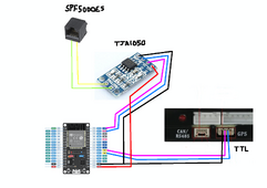
I am French and I use Google translate.
I would like to carry out the hardware part myself, do you think this diagram could work with your program?
How can I get your program?

mrconstantin
New Member
@mrconstantin
I am French and I use Google translate.
I would like to carry out the hardware part myself, do you think this diagram could work with your program?
How can I get your program?
View attachment 184529
Will work but Can controller to pin 4 5 , I modify ur pics to see it.
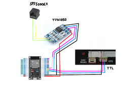
U find link in first page to my Google drive
https://drive.google.com/drive/folders/1EruM2z8ZyM2TMhrHV4PVuLqzRZ5zZji3?usp=sharing
MarcelVo
New Member
@mrconstantin Hi, I am the one awaiting the fake data to get my NEDAP / Solar Frontier Power Storage Inverter going. Got the ESP and the CAN connection up and running, I also managed to find online (altough in German, the messages the LG battery that is confirmed to work on my inverter sends out ; https://www.photovoltaikforum.com/t...-chem-resu-6-4ex-nedap-sma/?t=108629&start=10) I went trough this forum and found:”
It is a CANopen protocol according to CiA 438.
OD Indexes
RAW_CAN (2bytes)
00 10
09 10
0A 10
02 20
01 20
03 20
04 20
The above registers are transferred like this but they are actually the registers 0x1000 0x1009 0x100A etc. the registers/indexes
0x1000 device type or manufacturer (UINT32)
0x1009 Manufacturer HardwareVersion (String)
0x100A Manufacturer software version (string)
A list of possible manufacturers can be found on can-cia.org, but I suspect that the inverter does not expect any manufacturer, but only a few are accepted. the register queries are SDOs. These values are actively queried by the inverter and the memory must respond within 500ms. Such as,
0 Receive 01:14:25:610 Data frame Standard frame 00000351 8 45 02 4c 04 4c 04 00 00
Ladespannung 0x245/10 = 58.1V
Max. Ladestrom 0x44c/10 = 110.0A
Max. Ladestrom 0x44c/10 = 110.0A
Entladespannung 0x0/10 = 0.0V
These are PDOs that are permanently sent from the memory. The clock for this can be set via another register. The WR will need the PDOs once it has started operation.
Many inverters also work exclusively with PDO messages, this one does not, at least not when expecting a LG battery. However the inverter does have a generic battery selection where it might work without, hence only PDO’s. “
looking forward to hear from you. Thks and a Merry Christmas !
Last edited:
Paulfrench35
New Member
Will work but Can controller to pin 4 5 , I modify ur pics to see it.
View attachment 184548
U find link in first page to my Google drive
https://drive.google.com/drive/folders/1EruM2z8ZyM2TMhrHV4PVuLqzRZ5zZji3?usp=sharing
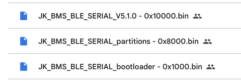
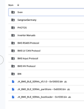
What should I use?
MarcelVo
New Member
Hi Paul, you need to load all 3 bin files to the ESP , please note the start adress stored in the file name. Bon Weekend !
Paulfrench35
New Member
Paulfrench35
New Member
So this one first : 0x1000.bin, then 0x8000.bin and and for finish 0x10000.bin ?
MarcelVo
New Member
I do not think it cares , just as long as you put the right files on the right address. It worked for me in the order as above 10000/8000/1000So this one first : 0x1000.bin, then 0x8000.bin and and for finish 0x10000.bin ?


