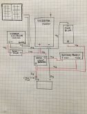
Is that block diagram accurate? Just wondering as it looks like your Victron batteryprotect is across the 200 amp breaker. The BP should be inline with the load that is to be automatically disconnected on low battery voltage.
Are your batteries in parallel or some other arrangement?
When determining the wire gauge to use you have to work with the lowest voltage the battery will be supplying to the load, and the expected draw by the load. Suppose your 1500 watt inverter is running full tilt. You might find that it actually draws 1700 watts due to losses in the inverter. If your low battery cut off is 11.5v that means about 150 amps (1700/11.5). The 2g from the battery to the breaker will cope with that. The current will exceed the 4g wire rating so you can expect it to heat up more than the insulation may be good for. Keep in mind that this is only with the inverter at full power. If it is only at that level for a short time that won't be a problem.
Is the intent of the 30 amp fuse between the CC and the battery to protect the wiring if it becomes shorted on the run between the CC and be fuse? If not, ie it's there to protect the CC, you could do away with it since the only fuse that will blow will also limit the power output from the CC. The Victron CC already limits its output current to 20amps.
The 10g from the CC to the battery is fine. It will only ever be carrying a maximum of 20amps.
You don't have a breaker in line with the solar input on the CC so when it comes time to disconnect the panels you should cover them up to avoid arc damage on the CC's input terminals or panel plugs.
Is the fuse block a 12v connection point for DC devices?


")
