diy solar

diy solar

circuit breaker spark

ohmboy

New Member
Joined
Feb 1, 2024
Messages
87
Location
Out West
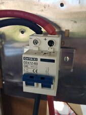
Hello, just got lucky that nothing burned down but I wanted to check the amps on my system because the BMS is not showing the charge amps only discharge. So what I did is put my multi-meter probes in the input side screws and as soon as I touched the meter positive probe to the positive screw on the circuit breaker, it sparked!!!
I put the multi-meter on 10A and put the positive lead to the 10A port.
I am now afraid to check the amps.
Where should I check the amps coming in from the solar charge controller?
And did I plug in my multi-meter properly?

Victron 100 | 30 SmartSolar Charge Controller
24v 105ah LiFePO4 battery
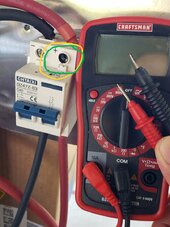


switch_spark_meter.jpgswitch_spark.jpg

thanks
 
I had a similar experience. I wanted to blame the breaker but after trying a few thing I found a crimped on wire feral sold the issue. I am perusing a come commercial bullet br4eaker resolution
 
I am not sure if you are saying that you put the Meter across the DC voltage +/- while the meter was in Amp mode? If so that was a direct short of the Meter and the meter either blew a 10A fuse or died if it had no fuse.
Your negative probes tip has burned off completely!

Assuming you had it inline with the positive terminal then you still would have had issues as the Meter can only handle 10Amps. Unless the load was less than 10A the meters fuse also blew.

Please clarify exactly how you had this hooked up.
 
Last edited:
I had a similar experience. I wanted to blame the breaker but after trying a few thing I found a crimped on wire feral sold the issue. I am perusing a come commercial bullet br4eaker resolution
Where can I safely check the amps coming in from the solar charge controller?
 
I am not sure if you are saying that you put the Meter across the DC voltage +/- while the meter was in Amp mode? If so that was a direct short of the Meter and the meter either blew a 10A fuse or died if it had no fuse.
Your negative probes tip has burned off completely!
I placed the positive probe of the meter on the positive screw of the circuit breaker, then put the negative probe of the meter to the negative screw of the circuit breaker. I did not put the meter across both screws.
Assuming you had it inline with the positive terminal then you still would have had issues as the Meter can only handle 10Amps. Unless the load was less than 10A the meters fuse also blew.
Victron app was showing 4.5A so I thought it was safe. Meter seems to still be working.
 
I placed the positive probe of the meter on the positive screw of the circuit breaker, then put the negative probe of the meter to the negative screw of the circuit breaker. I did not put the meter across both screws.
Huh!
If that is what you did then you did put it across the Positive and Negative.
When you put the positive probe into the Amp connection on the Meter it is putting both probes across an Internal Shunt that is basically a short circuit. The moment the Probes touch Positive and Negative the meter is going to short out and either blow a fuse (if it has one) or blow itself up.
The meter may still be working but I doubt that the Amp side of the meter is working. Open it up and see if you see a 10Amp fuse inside.

You need to be using a clamp on Meter that can read DC Amps if your going to be working on Solar.

Victron app was showing 4.5A so I thought it was safe. Meter seems to still be working.
 
If that is what you did then you did put it across the Positive and Negative.
When you put the positive probe into the Amp connection on the Meter it is putting both probes across an Internal Shunt that is basically a short circuit. The moment the Probes touch Positive and Negative the meter is going to short out and either blow a fuse (if it has one) or blow itself up.
Ahh, ok. I will not be doing this again! :)
Should I replace the circuit breaker?

The meter may still be working but I doubt that the Amp side of the meter is working. Open it up and see if you see a 10Amp fuse inside.
I will open it up and see if the fuse has blown.

You need to be using a clamp on Meter that can read DC Amps if your going to be working on Solar.
Next purchase will be a clamp on Meter. I have one on the wish list on amazon.


thanks again.
 
Ahh, ok. I will not be doing this again! :)
Should I replace the circuit breaker?
I would mainly because the Terminal screws head is pretty bad looking. It might be easier to just replace it now then have an issue one night and you cannot get the terminal loose.
I will open it up and see if the fuse has blown.

Next purchase will be a clamp on Meter. I have one on the wish list on amazon.
Which one?
thanks again.
Your Welcome.
 
I would mainly because the Terminal screws head is pretty bad looking. It might be easier to just replace it now then have an issue one night and you cannot get the terminal loose.
I will put one on order today.

Which one?
I am looking at this clamp meter. It shows that it can measure 40amps DC up to 400amps. Amazon clamp meter
 
I will put one on order today.


I am looking at this clamp meter. It shows that it can measure 40amps DC up to 400amps. Amazon clamp meter
There are many hall effect DC clamp meters out there. It is a must have. I also have a Victron shunt and solar assistant so I can look at the graph. I almost missed it until I looked at SA. Clamp meters are great if you are right there and now.
 
There are many hall effect DC clamp meters out there. It is a must have. I also have a Victron shunt and solar assistant so I can look at the graph. I almost missed it until I looked at SA. Clamp meters are great if you are right there and now.
What is SA?
 
Ok, I'm glad that it's not just me. 😁 ⚡

Sure, I used my Fluke with 10A range to measure current from 480VDC 7A string of PV panels.
No problem, right?
Well, they were connected to the input capacitor of my inverter. Blew the 11A 1000V fuse.

Another time I connected an inverter with 480VDC on its capacitors to another inverter, reverse polarity. Dumped the capacitor charge into reverse-polarity diode and blew fuses in combiner box. A comms module in the second inverter didn't work after that (didn't know if it ever did), but got replaced under warranty.

I bought Harbor Freight Aims 1000A clamp meter for $100.
Features include 1000A AC/DC, 10 mA resolution (on lower scale), AC inrush current.

 
Huh!
If that is what you did then you did put it across the Positive and Negative.
When you put the positive probe into the Amp connection on the Meter it is putting both probes across an Internal Shunt that is basically a short circuit. The moment the Probes touch Positive and Negative the meter is going to short out and either blow a fuse (if it has one) or blow itself up.
The meter may still be working but I doubt that the Amp side of the meter is working. Open it up and see if you see a 10Amp fuse inside.

You need to be using a clamp on Meter that can read DC Amps if your going to be working on Solar.
Yes, it looks like the glass fuse is blown. The continuity test failed and I am unable to tell if the filament inside is cut near one of the ends. I will have to use my CEN-TECH that I got for free at Harbor Freight. :)
 
Back
Top