diy solar

diy solar

Design of AGM & LiFePO4 / Solar system for my boat

Umm,... it looks great, but I'm seeing two things that concern me: 1)I don't see hold down straps on the batteries, and 2) if I am correct that the LiPo's are in parallel, I would think it would be better for them to be cabled parallel at the batteries themselves and run the Neg cable from the system to the Neg of one battery and the Pos of the system to the Pos of the OTHER battery so that the draw load and the charge remains even across both batteries.
 
Thanks for your comments.

Actually the batteries are now in battery boxes which are screwed into the battery shelf. The picture shown is one of the more final work-in-progress pictures, but not completed. As for the battery connections, I did hook them up as per the manufacturer's instructions, and all cables to the LiFePO batteries are the same length, but they are a bit longer than I'd like (33 inches). I'll consider the method you described as it may be a bit cleaner.
 
Last edited:
Thanks for your comments.

Actually the batteries are now in battery boxes which are screwed into the battery shelf. The picture shown is one of the more final work-in-progress pictures, but not completed. As for the battery connections, I did hook them up as per the manufacturer's instructions, and all cables to the LiFePO batteries are the same length, but they are a bit longer than I'd like (33 inches). I'll consider the method you described as it may be a bit cleaner.
I suggest that you heed tpenfield's cabling advice.
 
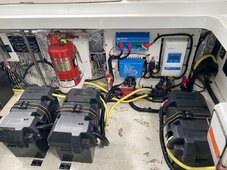
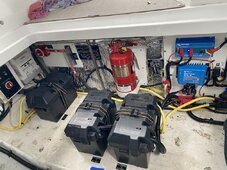
Here are a couple of 'finished' pictures . . . battery boxes and ID labels in place.

The system seems to be working well. Not much solar, due to cloudy/rainy days. I have not fired up the engines either, since overnight temperatures still get a bit cold.
.
IMG_6070.JPG
.
IMG_6071.JPG
.
 
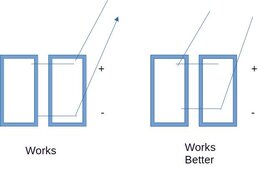
I still think your Parallel batteries are wrong (sub optimal). That Yellow going from the pair (Positive?) should be connected to the other battery in the pair, so the power, goes in one battery and out the other, that way the load and charge is spread evenly across both batteries. The way you have it, most of the load and charge is hitting the first battery and the one in parallel is just boosting it. The front battery is likely to starting having a different state of charge than the back one in this configuration.ParaBattConf.jpeg
 
I still think your Parallel batteries are wrong (sub optimal). That Yellow going from the pair (Positive?) should be connected to the other battery in the pair, so the power, goes in one battery and out the other, that way the load and charge is spread evenly across both batteries. The way you have it, most of the load and charge is hitting the first battery and the one in parallel is just boosting it. The front battery is likely to starting having a different state of charge than the back one in this configuration.View attachment 210284
I agree, I have seen as an example the Ford power stroke running two batteries the battery that was connected directly to the starter always failed first. A Motor-home I purchased that the previously installed inverter wired ( works style ) That battery failed.
 
I agree, I have seen as an example the Ford power stroke running two batteries the battery that was connected directly to the starter always failed first. A Motor-home I purchased that the previously installed inverter wired ( works style ) That battery failed.

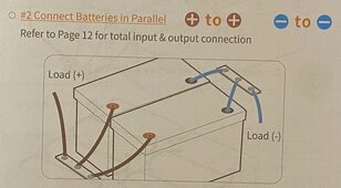
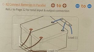
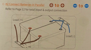
Well, maybe take it up with the folks at LiTime . . . Their connection instructions per the manual are this:

IMG_6077.JPG
.
Which I have done. As mentioned, the cables are a bit longer than I'd like (33 inches).
 
A quick update . . .

After some testing and trial operation . . .

The solar charging is working fine. Charging from shore power via the Xantrex Freedom SW 2012 and the ProNautic 1203P are both working fine.

Charging from the engine alternators . . . not so much.

I ran the Port (left) engine for 5-10 minutes. Input voltage to the Orion TR Smart ran a bit high (15.5v according to the iPhone App). The Orion kept going in an out of bulk charging mode . . . every 5-10 seconds. The LFP batteries were resting at about 13.2-13.3 volts. I made a few adjustments to the settings . . ., but it did not change much.

Then I ran the starboard (right) engine. The input voltage to the Orion went even higher 16volts !!! :eek: and fluctuated up and down from about 10 volts to 16 volts. After a few minutes the engine's control system said "I'm out-a here" and threw a critical warning, (setting off one of those annoying buzzers). I shut the engine down. I connected my diagnostic computer (Rinda Diacom) to the engine control system and cleared the fault code (It's a PCM 112 for those up on marine engine controllers). I disabled the Orion via the CB's and re-started the engine. At that point it appeared that the alternator was not charging the starter batteries. (oopppsey . . . o_O ) . . . The engine battery started off at 12.7 volts and went down to 12.3 volts within a few minutes.

So I left the system on solar charging and the batteries all became happy again. I checked a bunch of wiring, focusing on the 2 alternator/3 battery isolator and various points on the off grid component board. . . Tested a few things, took some voltage readings, etc. . . . Went in the house to have a beer. I'll be traveling for a few weeks, so I won't be back to it until mid-May at the earliest. I'm leaving the solar controller in charge while I'm gone.

A few of my observations . . .

I am getting voltage through the 2 alt/3 battery isolator even with the engines off . . . Which tells me it is a diode-based isolator. The Orion is sensing this voltage and trying to do something with it. There is about 12.8 volts to the CB ahead of the Orion. When I connect the CB the voltage goes down to about 7.5 volts . . . I did not notice that it was giving any output, but need to check some more.​

My isolator for trickle charging the engine batteries is not turning off properly. I beleive I have connected the FET activation wire to the wrong point in the solar charging circuit. So, that goes on the punch list.​
I'll need to check the engine fuses and CB's​
I think I'll re-engineer the Orion circuitry to use the ignition voltage to turn on/off.​
Probably will go to an FET-based isolator for the alternator/battery isolation and turn it 'on' via the ignition voltage.​
I could possibly go without the alt/batt isolator at all and just have each engine stand-alone with its battery. There is a parallel solenoid that can be momentarily used in a dead battery situation. If I went with a stand-alone configuration, I'd probably have the port engine/alternator do the LFP charging via the Orion. The starboard engine and its electrical is more voltage sensitive as it provides primary power to the engine control systems.

Fun, fun, fun
 
Last edited:
Well, maybe take it up with the folks at LiTime . . . Their connection instructions per the manual are this:

View attachment 210429
.
Which I have done. As mentioned, the cables are a bit longer than I'd like (33 inches).
Ok, but that is the same thing we are saying. Notice where the +/- to the system are: opposite ends. So if that is the way you have it connected, then you are right. Your photo of the system doesn't look like that though. This is what your photo looks like: (can you see the difference?)

24vBatteryConnectionBad.JPG
 
Last edited:
Ok, but that is the same thing we are saying. Notice where the +/- to the system are: opposite ends. So if that is the way you have it connected, then you are right. Your photo of the system doesn't look like that though. This is what your photo looks like: (can you see the difference?)
The photo obscures the view of a portion of the cables, but it is wired just like the manual shows. The diagrams in post #25 are different than the manual states. Now, I don't often read the manual for things like this, but in this case I did. . . . sort of . . .

I do see that you altered the diagram a little bit . . . Not sure that makes a world of difference. Actually, come to think of it, I connected the battery + and - leads to the same point on the bus bar . . . so I would get the same voltage on the bus bar in relation to the load.

IMG_6077a.png
 
Last edited:
Actually, I hoping to get some guidance on the Orion Tr Smart DC-DC charger . . . which is not happy, based on my testing.

I have the settings as follows if I recall correctly:

Set up as a charger
Standard alternator
Smart LiFePO4 battery
Using on/off jumper
Engine shutdown protection enabled

Not sure about the other settings.

Basic symptoms are

Orion is going in and out of bulk charging every 5-10 seconds

Alternator (Orion input) voltage is running high (15.5-16.0 volts). Engine system is giving an over-voltage warning.
 
The alternator should not be directly connected to the Orion. The Alternator connects to a battery (like a small lead-acid) and the Orion charges the LFP from that. The common setup is the alternator charges a lead-acid start battery and a DCDC to the house battery.

If you want to eliminate that extra battery, you need an alternator with an external regulator that can charge LFP without needing a DC-DC charger.
Yes, I was thinking that was an issue. Of course, I had someone tell me it would be OK, but perhaps it was not good guidance. Thank you. 👍
 
Let me provide a scenario that could easily occur. A fire starts in this battery compartment, and you need that fire extinguisher. Do you really want to reach in there while the lithium batteries might be flaring up or an explosion has occurred? It might be a lot safer to put that extinguisher where the chance for a fire or an explosion are a lot less. I keep mine in a hatch where there are no batteries. Otherwise, I like your installation very much. I may have to use two different chemistry batteries too. I'm now testing the 70hp outboard Yamaha with a standard 15amp alternator that is causing erratic 14v-18v alarms when the lithiums are at full charge. I don't know of a way to tap that alternator to add an external regulator. I'm still working on it. Maybe that isolator would help?
 
The photo obscures the view of a portion of the cables, but it is wired just like the manual shows. The diagrams in post #25 are different than the manual states. Now, I don't often read the manual for things like this, but in this case I did. . . . sort of . . .

I do see that you altered the diagram a little bit . . . Not sure that makes a world of difference. Actually, come to think of it, I connected the battery + and - leads to the same point on the bus bar . . . so I would get the same voltage on the bus bar in relation to the load.

View attachment 210888
I had hoped one of the engineers would have jumped in by now (I R NOT), but the difference in MY last diagram and the factory is that the CURRENT flows evenly across BOTH batteries in the factory diagram. You can have the same voltage at the buss bar, but one battery can be weaker than the other (Ahrs). In your picture, the cables from the batteries and the buss bar look to be identical size AND LENGTH. If that is the case, I would suspect you are OK (again, I hope one of the engineers will comment because I'm not an Expert but an Xspurt - an unknown drip under pressure). It all comes down to you want even current flow across all batteries. If you don't, the battery wired closest to the system takes the brunt of the load and will degrade faster, while the battery in the back may not fully charge (again, I may have that backwards - but the long and short is one dies before the other by an unusual margin.)
 
Let me provide a scenario that could easily occur. A fire starts in this battery compartment, and you need that fire extinguisher. Do you really want to reach in there while the lithium batteries might be flaring up or an explosion has occurred? It might be a lot safer to put that extinguisher where the chance for a fire or an explosion are a lot less. I keep mine in a hatch where there are no batteries. . . .
The fire extinguisher that you see in the pictures is a fixed mount automatic system, typically found it boats (often referred to as a 'halon' system, although I don't think they use halon). It is heat activated and also sends a signal to the engine ignition system and dash panel display. Here is a link if you would like to check it out. https://www.fireboy-xintex.com/marine-fire-extinguishing-systems/

According to USCG requirements, there are several other locations throughout the boat where portable fire extinguishers are located.
My apologies to you sir. I completely forgot about the Halon systems.
 
Just reading up on the Orion TR Smart, I plan to re-wire it to be remote activated. The User manual described a few ways of remote activation; a couple of them involving ignition key sensing.

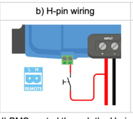
#1) Using the H-pin
Screenshot 2024-04-23 at 5.06.25 PM.png

The switch in the diagram would essentially be the ignition voltage when the key is turned to the 'on' position.

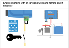
#2) L-Pin w/ jumper.

Screenshot 2024-04-23 at 5.09.09 PM.png

The second method pictured has more to do with the engine sensing override and charging when the engine is off.

I think my more simple approach is to use the 'H' pin method, as I am looking to charge only when the engines are running.

I'll need to do some investigating of the helm wiring (i.e. take the helm instrument panel apart) to isolate the ignition wire and see where I can tap into it. There is the halon system connections (mentioned in the post above) at the ignition switch, so that may provide a junction.

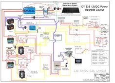
My wiring diagram is now looking like this . . .
CY-338-Power-Diagram-LiFePO4-4D3.jpg

Changes are:

1) The use of the ignition 'On' voltage to enable the solar lockout and enable the DC-DC charger.
2) Connection of the DC-DC charger directly to the Port side battery (rather than the alternator feed).

I won't be able to implement these changes for a few weeks as I am traveling. When I return to the boat, I'll also need to figure out if there is a problem with the alternator on the starboard engine, as it did not seem to be working after the testing craziness happened.
 
Last edited:
I had hoped one of the engineers would have jumped in by now (I R NOT), but the difference in MY last diagram and the factory is that the CURRENT flows evenly across BOTH batteries in the factory diagram. You can have the same voltage at the buss bar, but one battery can be weaker than the other (Ahrs). In your picture, the cables from the batteries and the buss bar look to be identical size AND LENGTH. If that is the case, I would suspect you are OK (again, I hope one of the engineers will comment because I'm not an Expert but an Xspurt - an unknown drip under pressure). It all comes down to you want even current flow across all batteries. If you don't, the battery wired closest to the system takes the brunt of the load and will degrade faster, while the battery in the back may not fully charge (again, I may have that backwards - but the long and short is one dies before the other by an unusual margin.)
There is one additional consideration that the installation manual makes note of in larger battery arrays (4P, etc), is to join the batteries together for balancing. They don't show it in the simple 2 parallel installation, but it still could apply, because it is one of the preparation steps outlined in the manual.

  1. Fully charge each battery to the same resting voltage.
  2. Connect the batteries together in parallel and let rest for 12-24 hours.
I could add a wire between the batteries (updated picture below), but I'm assuming they will tend to balance any way by virtue of their common connection at the bus bar.

FWIW - the battery cables are 2/0 (00) AWG with crimped and soldered connections each are 33" in length. I believe they are/were sized by the boat manufacturer for 100+ amps, based on the typical runs to the main power-consuming components in the boat. (Inverter, Engines, windlass, etc)

The most power consuming component on the boat is the 2000 watt inverter, which (theoretically) could draw about 165 amps at full load. The most I've seen it draw on a single load is 40 amps (powering the air conditioner). I have a small microwave oven that needs about 1000 watts to run, but the inverter won't run it unless it has 120 VAC shore power connected. I assume the microwave would need upwards of 100 amps into the inverter to generate the 1000 watts @ 120 VAC that it needs.

IMG_607X.png
 
Last edited:
Back
Top