diy solar

diy solar

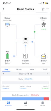
Deye 12K Single Phase Showing UPS-Load when there isn't one.

jhsolar

New Member
Joined
Nov 15, 2023
Messages
6
Location
UK
Hi All, Just setup Deye 12K SUN-12K-SG02LP1-EU-AM3 single phase inverter but am getting a strange reading in the monitoring section,
I Have Production, Grid, Battery, Load as expected, but I also have something called UPS-Load which is showing as being fed power.

I only have a connection into the Grid port, nothing to Gen or Load so am not sure what its talking about, any idea why this has shown up?
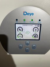
It doesn't show on the inverter display, only on the Monitoring.thumbnail_IMG_2804.jpgthumbnail_IMG_2805.png
 
Sounds to me to be the standby power - that required by the inverter to make AC voltage available.

For the size of the inverter, that looks pretty good to me.

My 10kW worth of Victron inverters burn about 55-60W, so 85W for 12kW seems pretty reasonable.
 
Hi All, Just setup Deye 12K SUN-12K-SG02LP1-EU-AM3 single phase inverter but am getting a strange reading in the monitoring section,
I Have Production, Grid, Battery, Load as expected, but I also have something called UPS-Load which is showing as being fed power.

I only have a connection into the Grid port, nothing to Gen or Load so am not sure what its talking about, any idea why this has shown up?
It doesn't show on the inverter display, only on the Monitoring.View attachment 183415View attachment 183416
CT's aren't installed correctly
 
CT's aren't installed correctly
I did wonder about the CT, I only have a single CT, the manual says to connect to pins 3 and 4 but was getting 0 usage showing, after some searching here people were saying pin 5 and 6 are correct and then the system works, my CT run is long, about 45m (147feet), and there is no way to make the run shorter, I did look to see if there was an offset or compensation setting but could not find one. Any ideas?
 
I did wonder about the CT, I only have a single CT, the manual says to connect to pins 3 and 4 but was getting 0 usage showing, after some searching here people were saying pin 5 and 6 are correct and then the system works, my CT run is long, about 45m (147feet), and there is no way to make the run shorter, I did look to see if there was an offset or compensation setting but could not find one. Any ideas?
I think the direction your ct us pointing in is simply wrong.
Ct ( in all Sunsynk and deye installs I have done) should be on pin 3+4
 
I think the direction your ct us pointing in is simply wrong.
Ct ( in all Sunsynk and deye installs I have done) should be on pin 3+4
on pin 3 and 4 the CT would show 0 watts in one direction (arrow pointing to inverter) and 22 watts in the other direction (arrow pointing to grid) (this is with a 4000 watt load) over the distance, I did a test with a space heater and using the CT at the standard length of 4 meters but got the same result of 0 watts in one direction 22 watts in the other (with a 1980 watt load), in pin 5 and 6 the CT is accurate to within around 80 watts at the 45 meter distance - arrow facing to grid.
 
I think the direction your ct us pointing in is simply wrong.
Ct ( in all Sunsynk and deye installs I have done) should be on pin 3+4
Update: so I did away with the CT all together and went for a Eastron SD230-Mosbus meter, it’s got rid of my little draw from grid and also now the inverter reading matches the utility meter, still have the “UPS-Load” icon. So it can’t be the CT, maybe it is just the inverter draw after all?
 

Attachments

  • IMG_2851.png
    IMG_2851.png
    132.7 KB · Views: 2
Update: so I did away with the CT all together and went for a Eastron SD230-Mosbus meter, it’s got rid of my little draw from grid and also now the inverter reading matches the utility meter, still have the “UPS-Load” icon. So it can’t be the CT, maybe it is just the inverter draw after all?
You inverter self usage is sometimes shown on the load port

You need to request a firmware update
 
Back
Top