diy solar

diy solar

DIY 280AH battery JK BMS JK-PB2A16S20P Canbus to SMA 5048

kommando

Solar Enthusiast
Joined
Aug 23, 2023
Messages
529
Location
UK
I built a DIY 16S battery using

Fogstar supplied Envision 280AH Grade B cells

Case was an self build XR-07 with JK-PB2A16S20P BMS and screen

It is now built and is at 69% charge out of the box and all cells are at 3.29V +/- .01V.

SMA SI 5048 EU is loaded with latest SI 6048 US firmware with Lithium support with closed loop Canbus comms. In the SMA list of compatible batteries are a number of Pylontech batteries.

Set JK BMS Canbus to Pylontech LV V1.2

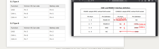
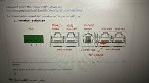
Used the JK docs on Canbus pinout to make a X over cable with SMA RJ45 on one end and JK RJ45 on the other. This did not work, SMA reported no Canbus comms, then found this post


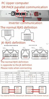
Where it is identified, amongst other issues, that the JK Can_L and Can_H pins are reversed.

As that now matches the SMA pinout I substituted the made up cable with a standard Cat5a ethernet cable.

Set SMA SI5048 to lithium, connected the SI5048 to the JK BMS and started it up, comms were good and SMA shows JK BMS battery SOC and, as it was still connected to the old lead acids, the lead acid bank voltage.

Weather forecast for tomorrow is rain rain and more rain so will take the opportunity to swap the leads from lead acids to the lithium. Will need to calibrate voltage and current on the JK and then will let it run and see how it performs.

The XR-07 case works well, it has the JK BMS ports correctly labelled, however the JK documentation is riddled with errors including ports labelled incorrectly and wrong pinouts.
 

Attachments

  • 319552008-49eae168-cc7f-4b36-818e-1f0d6f7d0fa2.png
    319552008-49eae168-cc7f-4b36-818e-1f0d6f7d0fa2.png
    68.6 KB · Views: 22
  • PXL_20240414_095453641.MP.jpg
    PXL_20240414_095453641.MP.jpg
    442.1 KB · Views: 20
Thanks for posting this! I'm just getting ready to wire my JKBMS up to my Sol-Ark and this is great information to have.
 
This pic is from the Battery case maker who labelled the RJ45's correctly and also has identified every pinout is back to front. JK live on an alternative universe connection wise LOL.

Did the final connection up today after lunch, the JK has lost its setting for capacitor burst discharge so had multiple short alarms and the BMS turning on and off until the SI's caps were full I was getting with lead acid. SMA SI charged the battery from 68% to 87% with none of the normal voltage peaks and frequency downrating of the Sunny Boy inverter. So with a sunny day tomorrow I have turned off float so the cell balancing can kick in, but the cells are staying balanced anyway even without me doing a top balance. Fogstar did a good job on the cells. Next days forecast is dire but Friday looks good so will try off grid.

As an experiment changed the BMS canbus protocol from Pylontech LV 1.2 to Goodwe and comms stayed up and running.
 

Attachments

  • JK BMS pinout.jpg
    JK BMS pinout.jpg
    107.2 KB · Views: 14
Last edited:
I tested last night and got my JK talking to the Sol-Ark 15k. A straight through cable would have probably worked but I swapped one pin for the GND connection.
1713444505346.jpeg
 
Thanks for the info. Can i just clarify does this mean that a standard ASS030720018 - VE.Can to CAN-bus BMS type B cable will work?
Yes, type b victron cable works with these (tested with a victron anyway! Not sure about other inverters)

Curious if you guys get the issue I have with this bms where the soc could jump from 85-90 ish straight to 100 under some conditions, if charge suddenly goes from low to high (4-5kw) and a single cell can jump to the rcv~100% soc voltage.
 
kommando, may I ask if your SMA inverter stop charging the battery the moment JKBMS SOC reached 100% even though the pack voltage hasn't reach 55.2V yet?
 
kommando, may I ask if your SMA inverter stop charging the battery the moment JKBMS SOC reached 100% even though the pack voltage hasn't reach 55.2V yet?
Sun has retired for a few days, rain rain rain, got to 95% yesterday but cell voltage did not get to 3.45 where I have the balancing set to turn on. However the cells are still within 0.010v of each other so unless the cell balance gets worse then balancing would not start even then.
 
Sun has retired for a few days, rain rain rain, got to 95% yesterday but cell voltage did not get to 3.45 where I have the balancing set to turn on. However the cells are still within 0.010v of each other so unless the cell balance gets worse then balancing would not start even then.
Hmm, let me know the result if your SMA inverter stopped charging right after the JKBMS reported SOC 100% to the inverter with battery pack voltage lower than 55.2V......
 
Hmm, let me know the result if your SMA inverter stopped charging right after the JKBMS reported SOC 100% to the inverter with battery pack voltage lower than 55.2V......
Hope it will work today, sun is out and battery is being charged.

When I set my SI5048 to Lithium I saw the SI target voltage was 55.2 but I decided I wanted the JK BMS to have full control so adjusted it to 56.2 on the SI. We will see if that is the correct decision hopefully later today.
 
Just tried a dumb charger to add 20A to the inverter input to the battery, had accidentally left the JK BMS setting for cons charge curr to 25A. JK BMS alarm came on and turned off incoming current into battery, SI did its frequency shifting and closed down the SB output. Changed the cons current charge to 100A and alarm cleared, SI dropped frequency and was charging at 40A ie 20A from inverter and 20A from charger. Good result.

Bat voltage is 54V currently
 
Last edited:
Good job I did not pay for the weather forecast, sun disappeared and the rain came back. Sun shortly to do down, got to 53.8V and 97% so no chance of 100%.
 
Well never getting to 100% at this rate, more rain but also the JK current meter is mince. I charged the battery at a constant rate and accurately measured the current and set this under the JK calibration. Under charging even with the solar it looks to stay accurate but with no charging and just the inverters using internal power I measure -0.8A but the JK is showing -2.5A. So overnight the JK % SOC is dropping by more than what the at rest voltage calculates as. No wonder the SOC on the JK comes in for a lot of flack for lack of accuracy.
 
So @kommando
The new jk bms, set to pylontech, with regular Ethernet cable, works with sunny island 6048? Wow.

Can you set the protocol via the jk app?
 
So @kommando
The new jk bms, set to pylontech, with regular Ethernet cable, works with sunny island 6048? Wow.

Can you set the protocol via the jk app?
Yes that is how it is set, have set it using the Bluetooth via the app on android phone and tablet and a PC using the RS485 link and both work. Have changed to the Goodwe Canbus which also works but not sure if there are any advantages except that Pylontech LV seems to give the barest info possible. They may get round to doing the full SMA canbus eventually but it works on 2 others anyway.

My SI5048 is loaded with SI6048US firmware which suggests all my experiences would carry over fine.
 
Yes that is how it is set, have set it using the Bluetooth via the app on android phone and tablet and a PC using the RS485 link and both work. Have changed to the Goodwe Canbus which also works but not sure if there are any advantages except that Pylontech LV seems to give the barest info possible. They may get round to doing the full SMA canbus eventually but it works on 2 others anyway.
Thanks! I may try it out
 
Added another inverters output to the JK BMS battery bank and the Sun came out, as soon as the 100% SOC threshold voltage set in the app was met the % SOC jumped from 93% to 100%. Have not turned on float so battery is being top balanced and neither the JK or SI has throttled the inverter input.
 
The balancing worked so dropped the target voltage on the JK to 3.45V per cell from 3.50V, the SI immediately increased its frequency and the charging stopped. Turned on a 600w load and the SI ramped the inverters up to 700w, reset the cell volts to 3.5V and full flow resumed. So the JK is controlling the SI as the target voltage set on the SI of 56.2V has never been reached.

Just checked the target voltage on the SI, its been dropped to 55v which it must have got from the JK at its set to 55.2V. The SI has started to frequency shift and the voltage is stable at 55.3V and then falls gently before the throttling eases off as a cloud goes over.
 
Last edited:
The balancing worked so dropped the target voltage on the JK to 3.45V per cell from 3.50V, the SI immediately increased its frequency and the charging stopped. Turned on a 600w load and the SI ramped the inverters up to 700w, reset the cell volts to 3.5V and full flow resumed. So the JK is controlling the SI as the target voltage set on the SI of 56.2V has never been reached.

Just checked the target voltage on the SI, its been dropped to 55v which it must have got from the JK at its set to 55.2V. The SI has started to frequency shift and the voltage is stable at 55.3V and then falls gently before the throttling eases off as a cloud goes over.
So the si changes it's voltage settings based on the bms? That's very interesting.
 
Back
Top