cs1234
Solar Wizard
- Joined
- May 9, 2022
- Messages
- 2,305
Probably work great, so long as they are evenly applied across the whole outer surface of the cells and not a little bungee cord.If that’s the case just a few loops of Kapton tape would work..


Probably work great, so long as they are evenly applied across the whole outer surface of the cells and not a little bungee cord.If that’s the case just a few loops of Kapton tape would work..
I know the issue was already discovered to be a wiring mistake, but I thought I'd join the others who believe your charging and cutout voltages are a bit high. I would recommend floating at 3.5v/cell (so set 56.0v on your charge controller), and cutting out at 3.6v/cell (set on the BMS for battery protection). You don't want to ever exceed (or spend much time at) 3.65v, and there's no guarantee that the BMS's voltage calibration is spot on. You go overvoltage just a little bit on a cell, and it will expand rapidly. So, while the peak of 57v you saw is within the absolute maximum pack voltage of 58.4v, what likely went wrong was a couple cells got full before the rest and exceeded their maximum rated voltage of 3.65v because other cells in series with them were still at 3.55v, having not yet reached full charge.57vdc is the highest bank voltage I can find. BMS is set for over voltage cutout 3.64v/cell. Active balancing enabled. It appeared to be doing its job.
I appreciate the feedback.I know the issue was already discovered to be a wiring mistake, but I thought I'd join the others who believe your charging and cutout voltages are a bit high. I would recommend floating at 3.5v/cell (so set 56.0v on your charge controller), and cutting out at 3.6v/cell (set on the BMS for battery protection). You don't want to ever exceed (or spend much time at) 3.65v, and there's no guarantee that the BMS's voltage calibration is spot on. You go overvoltage just a little bit on a cell, and it will expand rapidly. So, while the peak of 57v you saw is within the absolute maximum pack voltage of 58.4v, what likely went wrong was a couple cells got full before the rest and exceeded their maximum rated voltage of 3.65v because other cells in series with them were still at 3.55v, having not yet reached full charge.
Additionally, several people have done capacity tests at various target charge/float voltages, and the capacity loss at 3.5v is negligible—the biggest loss when running that voltage over the cells' absolute maximum voltage is the extra time it takes being held there to reach full charge as the current drops off quicker, slowing down the charging process. For solar systems that are expected to float multiple hours a day, this is no big deal, and the lower voltage will help mitigate the battery life impact caused by floating at 100% for hours each day. Furthermore, floating at 56.0v (instead of 57v) gives your cells that much more imbalance headroom to avoid cells that get full first exceeding their maximum cell voltage and needing the BMS cut-out (which failed in your case, due to the wiring error) to save them in the first place.
What would've been particularly interesting would be to see a screenshot of your BMS cell voltage figures right before you shut off power. That would be crucial information to have—I betcha you would have seen some cells over 3.7v (they tend to go overvoltage really quickly when it happens).
Overcharging is the most likely culprit in your case.Battery voltage was set to peak at 56.6v, just below 57volts. My Solar Assistant shows this.
Don't compress your cells. They are going to last so long on a solar system they will age out before they fail by expansion. I don't understand why people still do this.
As other stated the failure is likely short circuit between the cells. You need non-conductive dividers between the cells, don't just rely on the plastic.
NKON claims those new busbars to be flexible, by the look og them they do not look flexible, can you tell if they are? Also what cross section are they? (30mm2 or 40?)Battery busbars are new factory flexible units. Cells are new 280ah EVE units (Grade A)
All damage happened earlier today.
No Cabling overheated.
Red straps were minimal tension originally. Mostly to keep cells aligned for battery busbars.
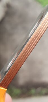
I measure them 20mm wide.NKON claims those new busbars to be flexible, by the look og them they do not look flexible, can you tell if they are? Also what cross section are they? (30mm2 or 40?)
May I ask you to please measure the thickness too?I measure them 20mm wide.
They are thick. Unable to as I'm no longer at batteries.May I ask you to please measure the thickness too?
I noticed in another of their videos they are measuring the cell depth and appears to be sorting them into a few buckets, perhaps to get the ideal overall length for each pack while accounting for manufacturing variation?Well, it may be caused by something else but never ever compress big and thin outer aluminium case cells like that, you are risking internal short and a lot of smoke or even fire. The most stressed cells in the corner are being damaged by every charge cycle, as there is strong local pressure from the bad fixture and that causes peeling of the separator layer to the uncompressed parts of the cell every time the internal "jelly roll" expands during charge. The only way for safe compression is equal pressure on whole side of the battery (flat surface and pressure prependicular to the cell surface).
You can use straps, but the object that pushes the cells together must be strong and flat (without any bending) and the force must be equal on whole side of the cell.