diy solar

diy solar

DIY LiFePo4 Solar Battery

Look I just gotta make it clear again to all of you . On LFP , LiFePo4,You go to 3.65V only on the first charge . Don't go there again or you will damage the SEI layer. If you don't know what that is then don't go there and look it up.
 
I wish I could find an explanation of bottom balance from an engineering perspective, because I just do not get how it helps on a pack that has a BMS. I get that if you are running without a BMS, you start at a nice spot across all cells and if they are matched properly with close internal resistance and capacity, over time they will stay withing a close range to each other. But if there is a BMS involved, it is always messing with that initial balance you achieved to begin with and I just do not understand how it would not nullify that.
 
I wish I could find an explanation of bottom balance from an engineering perspective, because I just do not get how it helps on a pack that has a BMS. I get that if you are running without a BMS, you start at a nice spot across all cells and if they are matched properly with close internal resistance and capacity, over time they will stay withing a close range to each other. But if there is a BMS involved, it is always messing with that initial balance you achieved to begin with and I just do not understand how it would not nullify that.
I'm with you. I did a bottom balance in lieu of using a cell balancing BMS. If there is a reason to bottom balance and subsequently run a cell balancing BMS after that I am interested in that logic as well.
 
Look I just gotta make it clear again to all of you . On LFP , LiFePo4,You go to 3.65V only on the first charge . Don't go there again or you will damage the SEI layer. If you don't know what that is then don't go there and look it up.
Have you started a thread on this? If not, we need to in the "Everything Else Storage" section. I would like to discuss this further for sure.
 
This site nicely presents the points @TCgreg and @robaroni are making:
Interesting link.

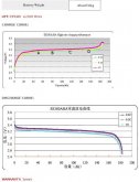
I can tell you from experience LFP cells hang for long time in their horizontal curve sweet spot but when the cells get to 3.1-3.2ish they start falling hard and fast even with a small discharge load. Bottom balance to 2.5v/cell should be done only with a programmable load that can quickly terminate discharge on time.
 
My understanding of bottom balancing is based on the BMS's you buy from ali-express and the like which are usually fitted on DIY packs and inside dropins . They are possibly quite different to what you use if you are coming from a RC background . Some of those balancers are different things altogether.

Balancing at a low value then allows the cells to fill up together to a point that at the most one cell goes over the top threshhold and everything turns off if a BMS is fitted. None of the other cells get there.

Now I believe the idea is to stay down round 90 % SOC max with your charger settings. If you don't have a BMS permanently connected on the negative line then how can you be sure one cell or more will not go over?

when the cells get to 3.1-3.2ish they start falling hard and fast
In fact when discharging, LFP cells spend the greater part of their capacity at around 3.2V. How will you tell if your cell is at A,B,Cor D in the below graph. (transpose those letters down to the lower discharge graph) See what I mean?

39940286_2205605823043791_2956259748279746560_n.jpg
 
Last edited:
Battery monitor for practical purpose is a decent compass.

Yes a LiFePO4 cell is in the meat of the bone at 3.2-3.4v. What I noticed watching my cellpro8 discharging each cell was that from 3.2 to 3.1 things started moving faster. At 3.1v, 2.5v wasn't far behind. The discharge cliff is real and fast.
 
Yes @b.james , my confusion may be about what a BMS is doing in my mind vs. what is being talked about here.
 
So you have a BMS on your battery then? Since you were trying to self-balance, I assumed you did not. Typically this whole top balance vs bottom balance is moot if you have a BMS as it is always balancing. Or were you trying to achieve your goal with the BMS removed?
I did the first bottom balance with the BMS disconnected.
 
My understanding of bottom balancing is based on the BMS's you buy from ali-express and the like which are usually fitted on DIY packs and inside dropins . They are possibly quite different to what you use if you are coming from a RC background . Some of those balancers are different things altogether.

Balancing at a low value then allows the cells to fill up together to a point that at the most one cell goes over the top threshhold and everything turns off if a BMS is fitted. None of the other cells get there.

Now I believe the idea is to stay down round 90 % SOC max with your charger settings. If you don't have a BMS permanently connected on the negative line then how can you be sure one cell or more will not go over?

In fact when discharging, LFP cells spend the greater part of their capacity at around 3.2V. How will you tell if your cell is at A,B,Cor D in the below graph. (transpose those letters down to the lower discharge graph) See what I mean?

View attachment 828
I see the problem you're using a specific battery curve and applying it to all LiFePo4's. I'm working off my specific battery curve and doing the same thing. Also I suspect that the batteries coming from my manufacturer (Tenergy) are already condition because I took several out of the lot and tested capacities and discharge characteristics with and without charging them to 3.65 volts first.

I can't really show the curve because the data sheet is too light.

I built a LiFePo4 circuit for my specific application but it should work for other LiFePo4's. The principle is that since almost all inverters shut off batteries at a low battery point all I need to do is make sure that charging never goes above 3.6 volts in any parallel leg in the series bank. I charge the batteries to 54.4 volts or 3.4 volts per leg. Since it's a 16 series bank it's always possible for one parallel leg to rise when my charger is dumping high current into the bank. (I could limit bank current but I don't because it would limit my "sell" capacity of my intertie)

So the principle is that the inverter cuts off at low voltage and the circuit cuts off any bank that rises above 3.60 volts. Most of the circuits from China have current fall off as the the voltage approaches the set point (in my case 3.60 volts) so you're getting very little control at your cut off voltage even with the active boards (Will found this out in one of his videos).
What I do is to clamp voltage the moment it hits 3.60 volts and keep it on till it drops to a specific lower point. ( this is called hysteresis for those who aren't familiar with it). I'm waiting for boards from my board house that should be here this week.

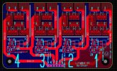
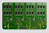
The circuit shows how I did it. Each board holds 4 of the circuit shown, enough for a 12V (4S) battery. The boards can be jumped together and there are LEDs to show any battery being clamped. I use 4 boards for my 48v system. I've set the clamp current at ~1.2 amps (it's adjustable), there are no large resistors, I've spread out the power over 6, 2.2 ohm SMD (surface mounted) resistors (3 series, 2 parallel = 3.3 ohms) at 2 watts each and isolated the heat from the main board. Changing the resistors changes the current clamp.

Beta testing should be done this week. If any of you guys are interested in boards maybe we can do a work out with Will.


LiFePo4 BMS-3.JPG
LiFePo4 BMS-2.JPG
 
Last edited:
Back
Top