This is part 2 of this thread post.
Here is SLD, major parts are complete DIY. I don't know if it will work and I also don't know if I have enough bonus years left to finish it.
Here is the Controller Monitor board, assembled but not yet tested. I had missing connections for temperature measurments so J21 (Digital IO) is re-purposed to analog inputs for temperature measurements. I was lucky I picked the Arduino Mega2560 analog pins for the Digital IO.
Completed the PV Fuse Interconnect board, only 4 fuses are installed just to show silk screen markings. I changed the 4.7k resistors to 68k for lower led current when a fuse blows and left blown for a while, the lit led is still visible.
Here is the PV combiner monitor. I used ACS712ELCTR-20A for sensing PV array current. There are 8 of them on a PCB that is 4 inches by 4-5/8 inches. It feeds two SCCs, each SCC is fed by 4 combined PV arrays. It outputs 8 pairs of PV voltages and currents to the monitor controller. I hope it works.
Update:
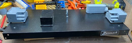
This was left out in post #1. It serves as a selectable ATS for most of the loads connected to the house circuit breaker. Loads connected to circuit breakers higher than 30 amperes are not routed to this ATS. I used sixteen ACS712ELCTR-30A (soldered at the bottom side of the pcb) to measure current for each load lines and with the stepped-down L1 and L2 voltages, each load line KVA can be calculated.
The above board controls four of these 30A 4-Channel Relay Module which connects each load line to either the grid or the inverter.


")