diy solar

diy solar

Do I need a LV cutoff with an inverter?

atatistcheff

Solar Enthusiast
Joined
Sep 20, 2019
Messages
176
I'm wondering if I need a low voltage cutoff if I'm using my LiFePO4 battery (Sinopoly) with an inverter? It seems that the 1500W pure sine wave inverter will automatically turn off somewhere around the minimum safe voltage for the battery anyway. Would a BMS really help here? I bought the cheapo $20 one that was an option with the RUiXU Sinopoly kit. It only supports up to 60A continuous so I also have a 200A relay which I was planning to use to interrupt the inverter power. But I'm really wondering if it's necessary? Thoughts?
 
If the inverter is the only load and you can rely on its low voltage cut out to turn off at a safe voltage, and not let you turn it back on until the voltage has gone back up again, I don't see a problem with that. What is the cut off per cell for the inverter? (divide cut off by number of cells)
 
The inverter's LV cutoff is 10V so that's 2.5V per cell. I'm not sure about the BMS, just emailed RUiXU to see if they will provide the specs. I should mention that I am using the BMS balance leads in any case. The Sinpoly cells they sent are keeping their balance very nicely although there is one that is about .15V above the others at full but that's not unusual, or so I understand. It's the LV cutoff that's in question here. Thanks!
 
I'm wondering if I need a low voltage cutoff if I'm using my LiFePO4 battery (Sinopoly) with an inverter? It seems that the 1500W pure sine wave inverter will automatically turn off somewhere around the minimum safe voltage for the battery anyway. Would a BMS really help here? I bought the cheapo $20 one that was an option with the RUiXU Sinopoly kit. It only supports up to 60A continuous so I also have a 200A relay which I was planning to use to interrupt the inverter power. But I'm really wondering if it's necessary? Thoughts?
Cell voltages are the important thing. I use a Victron Smart Battery Protect at ~12.8 for warning 12.7 for cutoff this is safe and protects in case your cells are out of balance at lower voltages.
 
Inverter cut off voltages are to protect the inverter. 10.5V is not suitable for lead, this voltage is to protect the FET which need a drive of 10V to go into saturation. Usually if an inverter goes into LV protect it shuts off and has to be turned off to reset. It is not advisable to switch incoming battery voltage from a protect relay as there is added resistance and these big power relays draw a lot of power to operate. Some inverters have external switch terminals that can be used. Those with a slide switch can have a wire soldered to it. One side of switch is always on battery. The other goes to control electronics. This is the side to switch. This is also where voltage is monitored so it is preferable to use relay contacts instead of electronics that may have a voltage drop. Momentary push buttons don't have this option. I wire all my inverters this way and only turn them on when needed.
 
Those with a slide switch can have a wire soldered to it. ... Momentary push buttons don't have this option.

Yes, that is the rub. My inverter has a momentary push button to turn it on/off. If I could find a way to turn it off electronically without having to put a powerful relay on the main power supply line it would be ideal. If anyone has any ideas on how that might be accomplished I'm all ears. Honestly though, I'm pretty sure the BMS I'm using cuts out at 10v just like the inverter so I'm still struggling to see why just allowing the inverter to shut off is a bad thing.

I need to actually test the BMS and see where it really cuts off. Who knows, maybe the inverter cuts of at a higher voltage anyway so it's a moot point. I'll update the thread when I have time to run some tests.
 
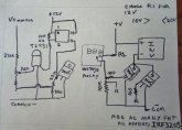
Instead of a relay you could use a few parallel FET on the negative return from the inverter. IRF3205 FET are cheap and rated at 110A. You can't use them at that as they still will generate a lot of heat but a few will get the total resistance down. Then it can be switched off without the heavy draw of a power relay all the time. If there are any realDIY people I can show a circuit using a TL431 and FET to do the voltage switch.
 
Instead of a relay you could use a few parallel FET on the negative return from the inverter. IRF3205 FET are cheap and rated at 110A. You can't use them at that as they still will generate a lot of heat but a few will get the total resistance down. Then it can be switched off without the heavy draw of a power relay all the time. If there are any realDIY people I can show a circuit using a TL431 and FET to do the voltage switch.
This is a concept that interests me. My question is say that I run 3 or 4 in parallel ,if that is possible, How much energy would they consume? I ask because my off grid system could have more than a week of no sun in the winter. Im not there in winter so batteries can handle a week without PV input when im just running cameras. I worry a powered FET or relay could be the straw that drinks the last of my storage.
 
About 2ma. Fet do not need any drive current except for the small pull down resistor on the gate. Once turned off that current drops as well.
 
Was just thinking about this last night . If I could control a switch on the line into the inverter I could turn it on only when I need it on preferably by some RF or IR control signal. The blue on light is quite bright at night and I don't like leaving it connected while I sleep either .
I would like to see what you have in mind with the Mosfets and I think I could build a suitable RF switch for little money.
How do you want to controll it. By phone, Pc, remote control.
 
Remote like a TV remote or door remote.
Perish the idea of turning on a phone all the time to see what voltage my system is at or what current is flowing . OK if my phone is on but that remote would be used mostly at night and I turn my phone off at night and file it in a biscuit tin to keep it quiet RF wise.
 
Here is the basic schematic. Searching for "digital voltage relay" will give you several under $13 that draw about 50ma on and 30ma off. I recommend at least 4 FET in parallel. These are rated about 100A. If you think you know more, then you can use less. Just remember if they get warm their resistance doubles. Then you won't need a voltage relay because the inverter will shut itself off. Gate has to be at least 10V and less than 20V or bad things happen. shoot for 12V.

For even less current you can use the schematic on the left with a TL431. The lower resistor on the FET provides positive feedback for better switching. The opto isolator can be replaced with a PNP trnsistor. Opto and TL431 can be found in any old phone charger. This draws about 2ma. Everyone wants a different voltage. Voltage divider calculators can be found to do this. Solve for 2.5V on the reference pin.

FETsws.jpg
 
I had one of those cheapie relays, but sourced from ebay instead. The contacts couldn't handle switching 100 amps and quickly degraded, became pitted etc. Not that I've tested one to find out but I'd rate them at being able to switch maybe 50 amps and be able to get a reasonable service life. Yes, will handle 200 amps, with warmth as a result, but don't expect to be able to switch it very many times.
 
Yes, will handle 200 amps, with warmth as a result, but don't expect to be able to switch it very many times.

Right, you get what you pay for. If I do use it, it should only have to switch any load at all in an under-voltage situation so these should be rare. In addition, loads of 120A should be equally rare. Thanks!
 
Cell voltages are the important thing. I use a Victron Smart Battery Protect at ~12.8 for warning 12.7 for cutoff this is safe and protects in case your cells are out of balance at lower voltages.
If you wired your BP to a relay without using a BMS i would like to see your schematic. I tried to get my BP 65 to work control a relay today without success. Thanks..
 
If you wired your BP to a relay without using a BMS i would like to see your schematic. I tried to get my BP 65 to work control a relay today without success. Thanks..
Thanks, I got it working. Don't have the smart BP but will use a program that is similar.
 
Back
Top